Download
1 / 47
520 likes | 811 Views
Organi sasi Komputer Handbook : Computer Organization and architecture 5 th Edition – Prentice Hall by William Stalling. Materi 3 Bus-Bus Sistem. Konsep Program. Sistem hardware tidak fleksibel

E N D
OrganisasiKomputerHandbook : Computer Organization and architecture 5th Edition – Prentice Hallby William Stalling Materi 3 Bus-Bus Sistem
KonsepProgram • Sistem hardware tidak fleksibel • Tujuan umum hardware untuk melakukan tugas-tugas yang berbeda, dengan jalan memberikan koresksi sinyal kontrol • Dengan mengubah hubungan (re-wiring),berarti memberikan set sinyal kontrol baru
Apa itu program? • Suatu urutan langkah-langkah kerja • Untuk tiap langkah,suatu operasi aritmatik atau logika dilakukan • Untuk tiap operasi, dibutuhkan pengaturan sinyal kontrol yang berbeda
Fungsi Unit Kontrol • Biasanya setiap operasi mempunyai kode yang unik • Misal ADD, MOVE • Suatu bagian hardware menerima kode dan mengirimkan sinyal kontrol • We have a computer!
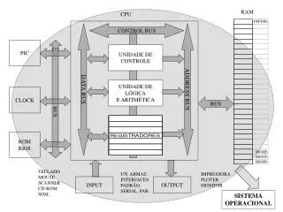
Komponen - komponen • Unit Kontrol dan ALU merupakan bagian yang terdapat dalam CPU (Central Processing Unit) • Data and instruksiperlu dimasukkan ke dalam sistem untuk mendapatkan suatu keluaran • Input/output • Media penyimpanan sementara (temporary storage)kode and hasil proses diperlukan • Memori utama
Putaran instruksi • Dua langkah: • Fetch • Execute
Putaran Fetch • Program Counter (PC) menyimpan alamat instruksi berikutnya untuk di fetch • Prosessor mem-fetch-kan instruksi dari lokasi memori yang ditunjuk oleh PC • Peningkatan PC • Instruksi dikirim ke Instruction Register (IR) • Prosessor menginterpretasikan instruksi dan melakukan aksi yang diperlukan
Putaran Eksekusi • Processor-memory • Data ditransfer antara CPU dan memori utama • Processor I/O • Data ditransfer antara CPU dan modul I/O • Data processing • Beberapa operasi aritmatik dan logika terhadap data • Control • Mengatur urutan-urutan operasi • Misalnya jump • Kombinasi proses di atas
Interupsi • Mekanisme oleh modul-modul lainnya (mis. I/O) untuk mengubah urutan normal proses yang berlangsung • Program • Misal : overflow, division by zero • Timer • Dihasilkan oleh internal processor timer • Digunakan dalam pre-emptive multi-tasking • I/O • Dari pengontrol I/O • Hardware failure • Misalnya bit paritas memori error
Lingkaran Interrupt • Ditambahkan ke dalam putaran instruksi • Prosessor mencek adanya interrupt • Diindikasikan oleh suatu interrupt signal • Jika tidak ada interrupt, fetch instruksi berikutnya • Jika interrupt ditunda: • Sedang mengksekusi program • Save context • Seting PC untuk memulai alamat interrupt handler routine • Proses interrupt • Kembalikan context dan lanjtkan program yang di interrupt
Multiple Interrupts • Disable interrupts • Processor will ignore further interrupts whilst processing one interrupt • Interrupts remain pending and are checked after first interrupt has been processed • Interrupts handled in sequence as they occur • Define priorities • Low priority interrupts can be interrupted by higher priority interrupts • When higher priority interrupt has been processed, processor returns to previous interrupt
Connecting • Seluruh unit Harustersambung • Koneksitiap unit berbeda-beda, di bedakanmenjadi: • Memori • Input/Output • CPU
Memory Connection • Menerimadanmengirimkan data • MenerimaAlamatlokasimemori • Menerima signal kendali • Baca • Tulis • Timing
Input/Output Connection(1) • Similar to memory from computer’s viewpoint • Output • Receive data from computer • Send data to peripheral • Input • Receive data from peripheral • Send data to computer
Input/Output Connection(2) • Receive control signals from computer • Send control signals to peripherals • e.g. spin disk • Receive addresses from computer • e.g. port number to identify peripheral • Send interrupt signals (control)
CPU Connection • Reads instruction and data • Writes out data (after processing) • Sends control signals to other units • Receives (& acts on) interrupts
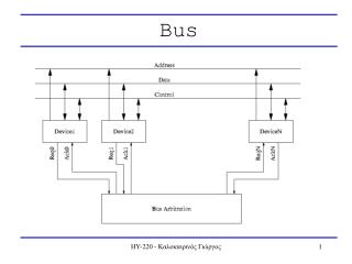
Buses • Terdapatbeberapakemungkinansisteminterkoneksi • Struktur yang seringdiditemuiadalah single dan multiple bus structure • Misal Control/alamat/Data bus (PC) • Unibus (DEC-PDP)
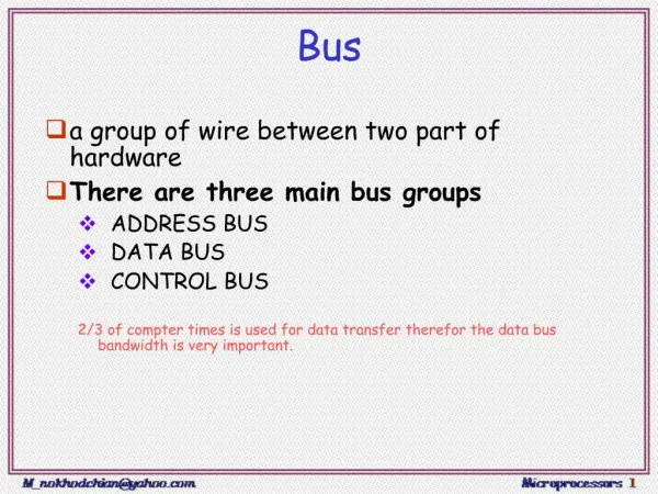
Apaitu Bus? • Sebuahjalurkomunikasimenghubungkanduaataulebihperalatan (device) • Biasanya broadcast • Sering di gabungkan • Beberapakanaldalamsatu bus • Misal data 32 bit di pisahdalam 32 single bit channel • Jalurdayamungkintidak di gambarkan (secara default ada)
Data Bus • Bertugasuntukmengusung data • Ingat!! Pada level initidakadaperbedaanantara “data” dan “instruksi”. • Faktorpenentuperformaadalahlebar data • Misal 8, 16, 32, 64 bit
Address bus • Identifikasisumberdantujuan data • Misal : CPU membutuhkanuntukmembacainstruksi (data) sesuaidenganlokasimemori yang di tunjuk. • Lebar bus menentukankapasitasmemorimaksimundarisebuah system • Misal 8080 memiliki 16 bit bus alamatsehinggaada 64k alamat memory.
Control Bus • Informasi control dan Timing • Signal untukbaca /tulisMemori • PermintaanInterupsi • Signal clock
Big and Yellow? • What do buses look like? • Parallel lines on circuit boards • Ribbon cables • Strip connectors on mother boards • e.g. PCI • Sets of wires
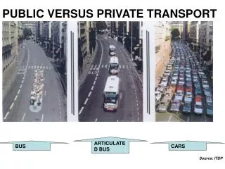
Single Bus Problems • Lots of devices on one bus leads to: • Propagation delays • Long data paths mean that co-ordination of bus use can adversely affect performance • If aggregate data transfer approaches bus capacity • Most systems use multiple buses to overcome these problems
Bus Types • Dedicated • Separate data & address lines • Multiplexed • Shared lines • Address valid or data valid control line • Advantage - fewer lines • Disadvantages • More complex control • Ultimate performance
Bus Arbitration • More than one module controlling the bus • e.g. CPU and DMA controller • Only one module may control bus at one time • Arbitration may be centralised or distributed
Centralised Arbitration • Single hardware device controlling bus access • Bus Controller • Arbiter • May be part of CPU or separate
Distributed Arbitration • Each module may claim the bus • Control logic on all modules
Timing • Co-ordination of events on bus • Synchronous • Events determined by clock signals • Control Bus includes clock line • A single 1-0 is a bus cycle • All devices can read clock line • Usually sync on leading edge • Usually a single cycle for an event
PCI Bus • Peripheral Component Interconnection • Intel released to public domain • 32 or 64 bit • 50 lines
PCI Bus Lines (required) • Systems lines • Including clock and reset • Address & Data • 32 time mux lines for address/data • Interrupt & validate lines • Interface Control • Arbitration • Not shared • Direct connection to PCI bus arbiter • Error lines
PCI Bus Lines (Optional) • Interrupt lines • Not shared • Cache support • 64-bit Bus Extension • Additional 32 lines • Time multiplexed • 2 lines to enable devices to agree to use 64-bit transfer • JTAG/Boundary Scan • For testing procedures
PCI Commands • Transaction between initiator (master) and target • Master claims bus • Determine type of transaction • e.g. I/O read/write • Address phase • One or more data phases
Foreground Reading • Stallings, chapter 3 (all of it) • www.pcguide.com/ref/mbsys/buses/ • In fact, read the whole site! • www.pcguide.com/