Download
1 / 19
190 likes | 216 Views
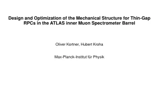
This article covers the design and implementation of enclosures for RPC Link Boards (LBs) in particle chambers, including cooling systems, electrical/optical cabling, backplane solutions, and assembly instructions.

E N D
Outline Introduction Periphery General Services Components, materials Manufacture, Assembly Installation Prototypes, Tests RE1/1 General Services Assembly Components, materials Installation Enclosures for the RPC Link Boards
Link Board, LB, (electronics card) is a link between chamber and counting room Box provides mechanical support for the LB Box offers means for cable routing and mounting Box offers cable strain relief LB replacement during maintenance possible Box includes individual cooling system Box provides electro-magnetic shield Box meets safety requirements Several LBs are grouped in to the same box 2 different electronic box designs Introduction
Covers RE1/2,3 & RE2 & RE3 & RE4 Design is derived from: -available space and maintenance requirements -signal cable characteristics (max 12 m cable length) -symmetry of CMS -number and size of cables and connectors -electronics heat dissipation Design consists: -max 16 LBs & 2 Control Boards, CB, per box -size of the LB (and CB) 237 x 160 mm -size of the box 400 x 400 x 300 mm -number of boxes 48 General, Periphery design
Cooling -Power dissipated per LB 10 W -> per box 180 W -Box includes individual cooling system made of copper -Heat transfer based on radiation and convection -Cooling pipe ID/OD 6/8mm, flow rate 2 l/min, pressure drop < 1 bar Services, Periphery design
Electrical and optical cabling -max 115 cables are routed from the back side of the box -cables & fibres are routed as round, connectors ready assembled -box is equipped with an Al sealing transit frame -Transit units are made of rubber -Transit units can handle various cable diameters -max 16 cables & 24 fibres are routed from the front side Services, Periphery design
Back plane solution -is constructed on a stand-alone LB frame -provides cross-connection between RPC cables and LB -provides cross-connection between LB - CB -provides connection for LV Services, Periphery design
Al box Plastic attachment units Copper cooling assembly Al LB frame Plastic/copper connectors Al/brass cable & fibre frame Al/EPDM rubber sealing transit units Mass 30 kg Components, materials, Periphery design
Design is derived from: -extreme space limitations for the box size -number and size of cables and connectors -location of services -space for the services Design consists: -6 LBs & 1 Control Boards, CB, per box -size of the LB (and CB) 245 x 120 mm (differs from periphery design) -size of the box 298 x 298 x 161 mm -number of boxes 12 General, RE1/1 design
Cooling -Power dissipated per LB 10 W -> per box 70 W -Cooling pipe ID/OD 6/8mm, flow rate 2 l/min, pressure drop < 1 bar Services, RE1/1 design
Electrical and optical cabling -62 cables & 12 fibres are routed from the back side of the box -Cable OD limited to 11.5 mm -Cable max diameter at the point where it is routed inside 8 mm -cables & fibres are routed as round, connectors ready assembled -box is equipped with an Al sealing transit frame -Transit units are made of rubber Services, RE1/1 design
Back plane solution -is constructed on a stand-alone LB frame Services, RE1/1 design
Back plane solution -provides cross-connection between *RPC – LB *I2C – CB *CB – DCS *LB – CSC *MLB – SLB *LB – CB * LV – LB&CB Services, RE1/1 design
Cooling system and LB frame assembled first This sub-assembly is installed into the box Assembly, RE1/1
Basically same materials as in periphery design Components, materials, RE1/1 design