Download
1 / 16
180 likes | 520 Views
Shear Design of Beams. CE 470 - Steel Design Class By: Amit H. Varma. Shear Strength. Beam shear strength is covered in Chapter G of the AISC specifications. Both rolled shapes and welded built-up shapes are covered.

E N D
Shear Design of Beams CE 470 - Steel Design Class By: Amit H. Varma
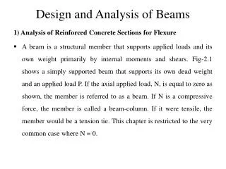
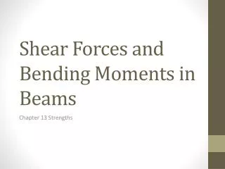
Shear Strength • Beam shear strength is covered in Chapter G of the AISC specifications. Both rolled shapes and welded built-up shapes are covered. • Rolled shapes is the focus here. Built-up shapes, commonly referred to as plate-girders are beyond the scope of our course. • Consider the behavior of beams in shear
Shear Strength • The web will completely yield long before the flanges begin to yield. Because of this, yielding of the web represents one of the shear limit states. • Taking the shear yield stress as 60% of the tensile yield stress. • This will be the nominal strength in shear provided there is no shear buckling of the web. • Shear buckling of the web depends on its h/tw ratio. • If the ratio is too large, then then web can buckle in shear elastically or inelastically.
Shear Buckling Elastic shear buckling Shear yielding
Shear Design Equations = area of web, the overall depth times the web thickness,, h= for rolled shapes, the clear distance between flanges less the fillet or corner radii, in. = for built-up welded sections, the clear distance between the flanges, in. = for built-up bolted sections, the distance between fastener lines, in. = for tees, the overall depth, in. = thickness of web, in.
Shear Design Equations The web plate shear buckling co-efficient,, is determined as follows: • For webs without transverse stiffeners and with except for the stem of tee shapes where • For webs with transverse stiffeners (G2-6) =5 when a/h >3.0 or a/h > where a= clear distance between transverse stiffeners, in.
Shear Design Equations 2. Transverse Stiffeners: Transverse stiffeners are not required where , or where the available shear strength provided in accordance with Section G2.1 for is greater than the required shear strength. The moment of inertia, , of the transverse stiffeners used to develop the available web shear strength, as provided in Section G2.1, about an axis in the web center for stiffener pairs or about the face in contact with the web plate for single stiffeners, shall meet the following requirement (G2-7) where (G2-8) and b is the smaller of the dimensions a and h.
Block Shear Failure of Beam • Block shear failure was considered earlier in tension member connections. • To facilitate the connections of beams to other beams so that the top flanges are at the same elevation, a short length of the top flange of one of the beams may be cut away, or coped. • If a coped beam is connected with bolts as shown, segment ABC will tend to tear out.
Block shear failure of beam ends • The applied load in the case of the beam will be the vertical reaction, so shear will occur along line AB and there will be tension along BC. Thus, the block shear strength will be a limiting value of the reaction. • Failure is assumed to occurred by rupture (fracture) on the tension area and rupture or yielding on the shear area. • Rn = 0.6 Fu Anv + Ubs Fu Ant 0.6 Fy Agv + Ubs Fu Ant • Where, phi=0.75
Example • Determine the maximum reaction, based on block shear, that can be resisted by the beam shown below. Treat the bolt end distance of 1.25 in. as standard. • The effective hole diameter is 3/4 + 1/8 = 7/8 in. • The shear areas are: • Agv = tw (2+3+3+3) = 0.30 (11) = 3.3 in2 • Anv = 0.300 [11 -3.5 (7/8)] = 2.381 in2
Block shear example • The net tension area is: • Ant = 0.300 [1.25 - 1/2 (7/8) ] = 0.2438 in2 • Since the block shear will occur in a coped beam with standard bolt end distance Ubs = 1.0. • Rn = 0.6 FuAnv + Fu Ant = 108.7 kips • With an upper limit of • Rn = 0.6 FyAgv + Fu Ant = 114.85 kips • Therefore, nominal block shear strength = 108.7 kips • Factored block shear strength for design = 0.75 x 108.7 = 81.5 kips.