Download

1 / 27

E N D
2. Moxon Beams Design & Building by WB5CXC
2006 Ham - Com
3. Moxon Beam Invented by Les Moxon � G6XN
Program Design by Dan Maguire AC6LA from formulas from L.B. Cebik W4RNL
Download Moxon Generator program:
www.moxonantennaproject.com/design.htm
4. Moxon Beam cont�d Two Element Folded Beam
Reduced size
50 Ohm Impedance (no matching required)
Elevations above � wavelengths have very little effect on SWR
~ 5.5 - 11 dB gain
Front to Back Ratio - ~ 25 � 30 dB
5. Moxon Beams cont�d Easy to Build
Can be made from wire or alum. Tubing
PVC, Wood, Fiberglass
Design Program
Put in the frequency & size of wire/tubing
Dimensions will be calculated
6. Moxon Beams cont�d Need to download MoxonGenerator.exe
This is the design program
Put in the center frequency you intend to operate and the wire or tubing size
Hit calculate � program will calculate the dimensions and spacing
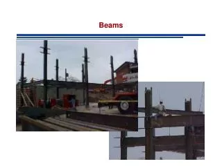
8. Beams in General Beam antennas come in all different designs
The most common is the straight element Yagi
2 � 4 element in HF bands
Many elements in the VHF, UHF bands
The length of the elements and the boom are inversely proportional to the frequency
The lower the frequency the longer the elements and boom
11. Building Moxon Beams Design your Moxon Beam
Measurements are critical as well as the wire or tubing used. If you are using different wiring or tubing size � recalculate for the different size of wire/tubing.
The Elements are isolated from ground and each other.
12. Building Moxon Beams cont�d Design a Moxon Beam for 10 Meters
Center frequency will be 28.5 Mhz
We will use # 14 wire
22. What does all this Mean? This data was generated using an Antenna modeling program (MultiNec & Eznec)
Antenna is modeled at 20 feet above ground, with average Ground conditions, and copper wire.
Modeled antenna is compared to � dipole (usually)
Can also be model in free space.
23. What does all this Mean? cont�d Gain 10.9 dB
dB = 10 log (Pout / Pin)
Gain is the number that corresponds to a log10 of 1.09
Gain is 12.3 (compared to � wave dipole)
You get 12.3 time the power in the main direction as compared with a � wave dipole
24. dB numbers that you should know 3 dB Double Power or � Power
10 dB � 10 times Power or 1/10 Power
20 dB � 100 times Power or 1/100 Power
25. What does all this Mean? cont�d Fr/Rear is 10.5 dB
This is a ratio of 11.22
Signals coming in from the rear has a reduction of 1/11.22
F/Back is ~ 23 dB
Signals are reduced by 1/199.5
34. Cost Material Cost for 2M Moxon
#6 Bare Copper wire - $ 2.75
1/2� PVC Tees $ .83
10� 1/2� PVC Pipe $ 1.29
Total $ 4.87
44. Moxon Programs & Etc. Moxon Antenna Design Program
http://www.moxonantennaproject.com/design.htm
Transmission Line Analyzer Program � TLDetails (Freeware)
http://www.ac6la.com/
Excel Based Antenna Modeling Program �MultiNec
http://www.ac6la.com/
45. Moxon Programs & Etc. Eznec Antenna Modeling Program
http://www.eznec.com/