Download
1 / 21
210 likes | 489 Views
The Link Layer. Dr. Adil Yousif. terminology: hosts and routers: nodes communication channels that connect adjacent nodes along communication path: links wired links wireless links LANs layer-2 packet: frame, encapsulates datagram. Link layer: introduction. global ISP.

E N D
The Link Layer Dr. Adil Yousif
terminology: hosts and routers: nodes communication channels that connect adjacent nodes along communication path: links wired links wireless links LANs layer-2 packet: frame,encapsulates datagram Link layer: introduction global ISP data-link layer has responsibility of transferring datagram from one node to physically adjacent node over a link Link Layer
datagram transferred by different link protocols over different links: e.g., Ethernet on first link, frame relay on intermediate links, 802.11 on last link each link protocol provides different services e.g., may or may not provide rdt over link transportation analogy: trip from Princeton to Lausanne limo: Princeton to JFK plane: JFK to Geneva train: Geneva to Lausanne tourist = datagram transport segment = communication link transportation mode = link layer protocol travel agent = routing algorithm Link layer: context Link Layer
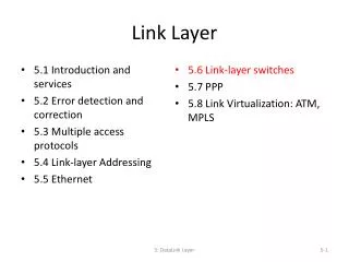
Link layer services • framing, link access: • encapsulate datagram into frame, adding header, trailer • channel access if shared medium • “MAC” addresses used in frame headers to identify source, dest • different from IP address! • reliable delivery between adjacent nodes • we learned how to do this already (chapter 3)! • seldom used on low bit-error link (fiber, some twisted pair) • wireless links: high error rates • Q: why both link-level and end-end reliability? Link Layer
Link layer services (more) • flow control: • pacing between adjacent sending and receiving nodes • error detection: • errors caused by signal attenuation, noise. • receiver detects presence of errors: • signals sender for retransmission or drops frame • error correction: • receiver identifies and corrects bit error(s) without resorting to retransmission • half-duplex and full-duplex • with half duplex, nodes at both ends of link can transmit, but not at same time Link Layer
in each and every host link layer implemented in “adaptor” (aka network interface card NIC) or on a chip Ethernet card, 802.11 card; Ethernet chipset implements link, physical layer attaches into host’s system buses application transport network link link physical Where is the link layer implemented? cpu memory host bus (e.g., PCI) controller physical transmission network adapter card Link Layer
Multiple access links, protocols two types of “links”: • point-to-point • PPP for dial-up access • point-to-point link between Ethernet switch, host • broadcast (shared wire or medium) • old-fashioned Ethernet • upstream HFC • 802.11 wireless LAN shared RF (e.g., 802.11 WiFi) shared RF (satellite) shared wire (e.g., cabled Ethernet) humans at a cocktail party (shared air, acoustical) Link Layer
Multiple access protocols • single shared broadcast channel • two or more simultaneous transmissions by nodes: interference • collision if node receives two or more signals at the same time multiple access protocol • distributed algorithm that determines how nodes share channel, i.e., determine when node can transmit • communication about channel sharing must use channel itself! • no out-of-band channel for coordination Link Layer
An ideal multiple access protocol given:broadcast channel of rate R bps desiderata: 1. when one node wants to transmit, it can send at rate R. 2. when M nodes want to transmit, each can send at average rate R/M 3. fully decentralized: • no special node to coordinate transmissions • no synchronization of clocks, slots 4. simple Link Layer
MAC protocols: taxonomy three broad classes: • channel partitioning • divide channel into smaller “pieces” (time slots, frequency, code) • allocate piece to node for exclusive use • random access • channel not divided, allow collisions • “recover” from collisions • “taking turns” • nodes take turns, but nodes with more to send can take longer turns Link Layer
Channel partitioning MAC protocols: TDMA TDMA: time division multiple access • access to channel in "rounds" • each station gets fixed length slot (length = pkt trans time) in each round • unused slots go idle • example: 6-station LAN, 1,3,4 have pkt, slots 2,5,6 idle 6-slot frame 6-slot frame 3 3 4 4 1 1 Link Layer
Channel partitioning MAC protocols: FDMA FDMA: frequency division multiple access • channel spectrum divided into frequency bands • each station assigned fixed frequency band • unused transmission time in frequency bands go idle • example: 6-station LAN, 1,3,4 have pkt, frequency bands 2,5,6 idle time frequency bands FDM cable Link Layer
Random access protocols • when node has packet to send • transmit at full channel data rate R. • no a priori coordination among nodes • two or more transmitting nodes ➜“collision”, • random access MAC protocol specifies: • how to detect collisions • how to recover from collisions (e.g., via delayed retransmissions) • examples of random access MAC protocols: • slotted ALOHA • ALOHA • CSMA, CSMA/CD, CSMA/CA Link Layer
CSMA (carrier sense multiple access) CSMA: listen before transmit: if channel sensed idle: transmit entire frame • if channel sensed busy, defer transmission • human analogy: don’t interrupt others! Link Layer
collisions can still occur: propagation delay means two nodes may not hear each other’s transmission collision: entire packet transmission time wasted distance & propagation delay play role in in determining collision probability CSMA collisions spatial layout of nodes Link Layer
CSMA/CD (collision detection) CSMA/CD:carrier sensing, deferral as in CSMA • collisions detected within short time • colliding transmissions aborted, reducing channel wastage • collision detection: • easy in wired LANs: measure signal strengths, compare transmitted, received signals • difficult in wireless LANs: received signal strength overwhelmed by local transmission strength • human analogy: the polite conversationalist Link Layer
CSMA/CD (collision detection) spatial layout of nodes Link Layer
“Taking turns”MAC protocols channel partitioning MAC protocols: • share channel efficiently and fairly at high load • inefficient at low load: delay in channel access, 1/N bandwidth allocated even if only 1 active node! random access MAC protocols • efficient at low load: single node can fully utilize channel • high load: collision overhead “taking turns” protocols look for best of both worlds! Link Layer
data data poll “Taking turns” MAC protocols polling: • master node “invites” slave nodes to transmit in turn • typically used with “dumb” slave devices • concerns: • polling overhead • latency • single point of failure (master) master slaves Link Layer
“Taking turns” MAC protocols token passing: • control tokenpassed from one node to next sequentially. • token message • concerns: • token overhead • latency • single point of failure (token) T (nothing to send) T data Link Layer
Questions These slides are adapted from Computer Networking: A Top Down Approach Jim Kurose, Keith RossAddison-WesleyMarch 2012