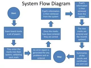
Protein Amplification System Design | PoPS & P22 Device-Level Diagram
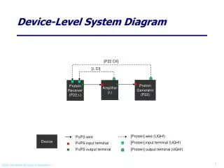
Explore the device-level system diagram of a protein generator, receiver, and amplifier with relevant parts and a possible DNA layout. Understand how PoPS and P22 components interact in this amplification system.

Protein Amplification System Design | PoPS & P22 Device-Level Diagram
E N D
Presentation Transcript
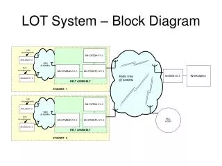
Device-Level System Diagram [P22 CII] [l CI] Protein Generator (P22) Protein Receiver (P22;l) Amplifier (l) [Protein] wire (UGH!) PoPS wire Device [Protein] input terminal (UGH!) PoPS input terminal PoPS output terminal [Protein] output terminal (UGH!)
Parts-Level & Possible DNA Layout P22 CII CI cI P22cII RBS TT RBS TT B0034? C0051? B0015? R#### B0034? C0053? B0015? R#### Amplifier [PoPS PoPS] Note: The above amplifier device is just a protein generator device with a downstream operator. Protein Generator [PoPS P22 cII] Protein Receiver [P22 cII; l cI PoPS]