Download
1 / 9
90 likes | 117 Views
Learn about the coordinated concept of building and maintenance approach for the finalized power core design at the ARIES Meeting. Detailed sequence of port maintenance procedures including extractor movements. Explore the plan view of the maintenance approach using mobile transfer airlock for effective blanket module removal. Enhance confidence in maintenance scheme through additional construction details.

E N D
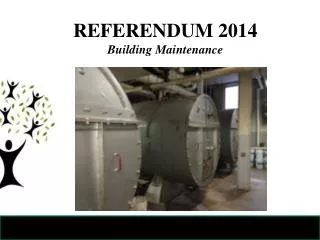
Maintenance and BuildingConceptual Approach L. M. Waganer The Boeing Company ARIES Meeting University of California, San Diego 14-15 June 2006
Coordinated Design Approach The nominal maintenance approach has been selected and the power core design finalized. Next, the building and maintenance approach has to be developed in concert.
Power Core General Configuration These graphics represent our current 3-field period, port maintenance approach 19 m
Sequence of Port Maintenance Extractor is located inside the Transfer Chamber ready to remove and set aside the bioshield plug and then remove the auxiliary shielding inside the vacuum vessel port
Sequence of Port Maintenance The Extractor now moves inside the vacuum port and removes the port shield
Sequence of Port Maintenance The Extractor now access the port blanket for extraction and delivery to the transfer airlock
Sequence of Port Maintenance The Extractor now access the inner blanket modules for extraction and delivery to the transfer airlock Note that the opening created by the port blanket must be large than is currently shown to accommodate the large inner blanket modules.
Plan View of Maintenance Approach Mobile Transfer Airlock • Three Transfer Chambers are permanently located outside the ports. • The Extractor equipment enters through an access door • The Extractor removes the Bioshield Port Plug and sets aside • The Extractor then moves inside and removed the port shield, retracts it, rotates and places it in the mobile airlock • Mobile Airlock goes to Hot Cell • The sequence is repeated until all blanket modules are removed • This can happen all ports simultaneously Power Core Transfer Chamber Extractor Access Door
Next Actions • This level of detail probably suffices to prove feasibility • Additional detail will be added to increase the confidence in the selected maintenance scheme and building definition • Some consideration should be added for construction approach with Reactor Building • Added details for Hot Cell, steam generators and turbines could be provided, if required.