Download
1 / 29
310 likes | 532 Views
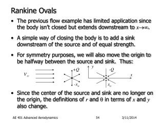
Reliable Rankine Cycle : One OFWH & Many CFWHS…. P M V Subbarao Professor Mechanical Engineering Department I I T Delhi. A truly Concurrent Design ……. 6. 5. 4. 3. 2. 1. GSC. DC. 3. 2. 5. 1. 4. 6. GSC. DC. Gas Release Mechanism in Deaerator. The Mechanical Deaerator.

E N D
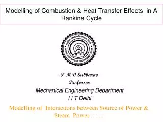
Reliable Rankine Cycle : One OFWH & Many CFWHS…. P M V Subbarao Professor Mechanical Engineering Department I I T Delhi A truly Concurrent Design ……
6 5 4 3 2 1 GSC DC 3 2 5 1 4 6 GSC DC
The Mechanical Deaerator • Corrosion of iron or steel in boilers or boilers feed water piping is caused by three fundamental factors: • 1. Feedwater temperature • 2. Feed water ph value • 3. Feedwater oxygen content Temperature and ph value influence the aggressiveness of corrosion. • The higher the temperature, and the lower the pH value the increased aggressiveness of the feedwater. • The dissolved oxygen content of the feedwater is a large factor in determining the amount of corrosion that will take place. • The presence of oxygen, and other non-condensable gases, in the feedwater is a major cause of corrosion in the feedwater piping, boiler, and condensate handling equipment.
Deaeration is based on two scientific principles. • The first principle can be described by Henry's Law. • Henry's Law asserts that gas solubility in a solution decreases as the gas partial pressure above the solution decreases. • The second scientific principle that governs deaeration is the relationship between gas solubility and temperature. • Easily explained, gas solubility in a solution decreases as the temperature of the solution rises and approaches saturation temperature. • A deaerator utilizes both of these natural processes to remove dissolved oxygen, carbon dioxide, and other non-condensable gases from boiler feedwater.
Correct deaerator operation requires a vessel pressure of about 20 – 30 kPa above atmospheric, and • a water temperature measured at the storage section of 50C above the boiling point of water at the altitude of the installation. • There should be an 45 – 60 cm steam plume from the deaerator vent, this contains the unwanted oxygen and carbon dioxide. • The following parameters should be continuously monitored to ensure the correct operation of the deaerator. • Deaerator operating pressure. • Water temperature in the storage section.
Deaerator Principles • Deaeration is the mechanical removal of dissolved gases from the boiler feedwater. • There are three principles that must be met in the design of any deaerator. • 1. The incoming feedwater must be heated to the full saturation temperature, corresponding to the steam pressure maintained inside the deaerator . • This will lower the solubility of the dissolved gases to zero. • 2. The heated feedwater must be mechanically agitated. • This is accomplished in a tray deaerator by first spraying the water in a thin film into a steam atmosphere. • Creating a thin film reduces the distance the gas bubble has to travel to be released from the water.
Next, the water is cascaded over a bank of slotted trays, further reducing the surface tension of the water. • This allows for the removal of any gases not liberated by the initial spraying. • 3. Adequate steam supply must be passed through the water, in both the spray section and the tray section to sweep out the gases from the water.
Sequence of FWHs HP CFWHs – one OFWH – LP CFWHs
Deaerator as Ith OFWH D BFP
Steam FW C DC DS Condensate Bled steam -TTD T -TTD=Terminal temperature difference C=Condenser C DS DC DC=Drain cooler DS=Desuperheater L Feedwater heater with Drain cooler and Desuperheater
Steam FW FW C DC Condensate Bled steam + TTD T Feedwater C DC L Feedwater heater with Drain cooler
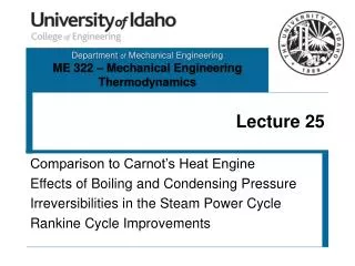
Pmax=8 MPa,480oC , Pc=0.04 MPa Reheat-Regenerationcycle Regeneration cycle Improvement in efficiency due to reheating in a reheat-regeneration cycle