Download
1 / 35
350 likes | 541 Views
Modelling of Combustion & Heat Transfer Effects in A Rankine Cycle. P M V Subbarao Professor Mechanical Engineering Department I I T Delhi. Modelling of Interactions between Source of Power & Steam Power ……. Fuel Model. Analysis of Fuel. Proximate Analysis & Ultimate Analysis.

E N D
Modelling of Combustion & Heat Transfer Effects in A Rankine Cycle P M V Subbarao Professor Mechanical Engineering Department I I T Delhi Modelling of Interactions between Source of Power & Steam Power ……
Analysis of Fuel • Proximate Analysis & Ultimate Analysis. • Proximate analysis - to determine the moisture, ash, volatiles matter and fixed carbon • Ultimate or elementary analysis - to determine the elemental composition of the coal • The Energy content -- CFRI Formulae -- • Low Moisture Coal(M < 2% ) -- CV (Kcal/kg) = 71.7 FC + 75.6 (VM-0.1 A) - 60 M • High Moisture Coal(M > 2%) -- CV(kcal.kg) = 85.6 {100 - (1.1A+M)} - 60 M • Where, M, A, FC and VM denote moister, ash , fixed carbon and Volatile mater (all in percent), respectively.
Fuel Model Ultimate Analysis of fuel: Gravimetric : Percentage of carbon : x --- Number of k moles, X = x/12 Percentage of combustible hydrogen : y --- Number of atomic kmoles Percentage of available oxygen for combustion : k --- Number of atomic kmoles, K = k/16 Percentage of sulfur: z – Number of atomic kmoles, Z = z/32 Equivalent chemical formula : CXHYSZOK Equivalent Molecular weight : 100 kgs. Also called as Representative Chemical Formula (RCF). A mathematical model for useful part of 100kg of fuel.
Fuel Model Ultimate Analysis of fuel: Gravimetric : Percentage of carbon : x --- Number of k moles, X = x/12 Percentage of combustible hydrogen : y --- Number of atomic kmoles Percentage of available oxygen for combustion : k --- Number of atomic kmoles, K = k/16 Percentage of sulfur: z – Number of atomic kmoles, Z = z/32 Equivalent chemical formula : CXHYSZOK Equivalent Molecular weight : 100 kgs. Also called as Representative Chemical Formula (RCF). A mathematical model for useful part of 100kg of fuel.
Model Testing for Determination of important species Water Flow Rate Air Flow Rate Flue gas Analysis Fuel Flow Rate
Results of Model Testing. • For a given fuel and required steam conditions. • Optimum air flow rate. • Optimum fuel flow rate. • Optimum steam flow rate. • Optimum combustion configuration!!! • Realization of MATtr Theory • Mixing: Fuel preparation systems. • Air: Draught systems. • T : Preheating of fuel. • t : Dimensions of combustion chamber. • r: Turbulence generation systems.
Stoichiometry of Actual Combustion • CXHYSZOK +e 4.773 (X+Y/4+Z-K/2) AIR→ P CO2 +Q H2O +R SO2 + T N2 + U O2 + V CO • Conservation species: • Conservation of Carbon: X = P+V • Conservation of Hydrogen: Y = 2 Q • Conservation of Oxygen : K + 2 e (X+Y/2+Z-K/2) = 2P +Q +2R +2U+V • Conservation of Nitrogen: 2 e 3.76 (X+Y/2+Z-K/2) = T • Conservation of Sulfur: Z = R
Stoichiometric Analysis of Furnace at Site • CXHYSZOK +e 4.76 (X+Y/2+Z-K/2) AIR + Moisture in Air + Ash Moisture in fuel→ P CO2 +Q H2O +R SO2 + T N2 + U O2 + V CO + W C + Ash • Mass of air: e*4.76* (X+Y/2+Z-K/2) *28.89 kg. • Mass of Coal: 100 kg. • Excess Air: (e-1)*4.76* (X+Y/2+Z-K/2) *28.89 kg.
Composition of Gas in A Furnace • For every 100 kg of Coal (A Representative Molecular Weight). • CXHYSZOK +e 4.76 (X+Y/4+Z-K/2) AIR + Moisture in Air + Ash Moisture in fuel → P CO2 +Q H2O +R SO2 + T N2 + U O2 + V CO + W C + Ash
Dry Exhaust gases: P CO2 +R SO2 + T N2 + U O2 + V CO kmols. • Volume of gases is directly proportional to number of moles. • Volume fraction = mole fraction. • Volume fraction of CO2 : x1 = P * 100 /(P +R+ T + U + V) • Volume fraction of CO : x2= VCO * 100 /(P +R+ T + U + V) • Volume fraction of SO2 : x3= R * 100 /(P +R+ T + U + V) • Volume fraction of O2 : x4= U * 100 /(P +R+ T + U + V) • Volume fraction of N2 : x5= T * 100 /(P +R+ T + U + V) • These are dry gas volume fractions. • Emission measurement devices indicate only Dry gas volume fractions.
Measurements: • Volume flow rate of air. • Volume flow rate of exhaust. • Dry exhaust gas analysis. • x1 +x2 +x3+ x4 + x5 = 100 or 1 • Ultimate analysis of coal. • Combustible solid refuse. nCXHYSZOK +en 4.76 (X+Y/4+Z-K/2) AIR + Moisture in Air + Ash & Moisture in fuel → x1CO2 +x6 H2O +x3 SO2 + x5 N2 + x4 O2 + x2 CO + x7C + Ash
nCXHYSZOK +en 4.76 (X+Y/4+Z-K/2) AIR + Moisture in Air + Ash & Moisture in fuel → x1CO2 +x6 H2O +x3 SO2 + x5 N2 + x4 O2 + x2 CO + x7C + Ash • x1, x2,x3, x4 &x5 : These are dry volume fractions or percentages. • Conservation species: • Conservation of Carbon: nX = x1+x2+x7 • Conservation of Hydrogen: nY = 2 x6 • Conservation of Oxygen : nK + 2 ne (X+Y/4+Z-K/2) = 2x1 +x2 +2x3 +2x4+x6 • Conservation of Nitrogen: e n 3.76 (X+Y/4+Z-K/2) = x5 • Conservation of Sulfur: nZ = x3
nCXHYSZOK +en 4.76 (X+Y/4+Z-K/2) AIR + Moisture in Air + Ash & Moisture in fuel → x1CO2 +x6 H2O +x3 SO2 + x5 N2 + x4 O2 + x2 CO + x7C + Ash • Re arranging the terms (Divide throughout by n): CXHYSZOK +e 4.76 (X+Y/4+Z-K/2) AIR + Moisture in Air + Ash & Moisture in fuel → (x1/n)CO2 +(x6/n) H2O +(x3/n) SO2 + (x5/n) N2 + (x4/n) O2 + (x2/n) CO + (x7/n) C + Ash CXHYSZOK +e 4.76 (X+Y/4+Z-K/2) AIR + Moisture in Air + Ash Moisture in fuel → P CO2 +Q H2O +R SO2 + T N2 + U O2 + V CO + W C + Ash
Specific Flue Gas Analysis • For each kilogram of fuel: • Air : e 4.76 (X+Y/2+Z-K/2) * 29.9 /100kg. • CO2 : P * 44/100 kg. • CO : V * 28/100 kg. • Oxygen in exhaust : 32 * U/100 kg. • Unburned carbon: 12*12/100 kg.
First Law Analysis of Furnace at Site • CXHYSZOK +e 4.76 (X+Y/2+Z-K/2) AIR + Moisture in Air + Ash Moisture in fuel→ P CO2 +Q H2O +R SO2 + T N2 + U O2 + V CO + W C + Ash • S Qlosses + n air hair + n fuel hfuel = n fluegas hfluegas + S W • Unburned carbon losses. • Incomplete combustion losses. • Loss due to ash. • Radiation and Convection Losses from Furnace Surface
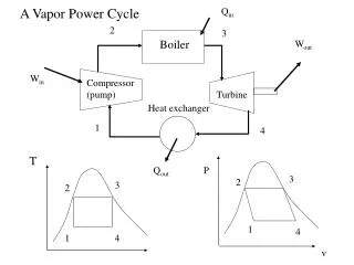
Capacity of Flue Gas Total Thermal Power available with flue gas: Rate of steam production:
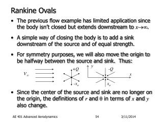
3 5 2s 2f 4 2 1 6 s
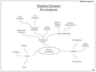
Paths of Steam and Gas Drum Water walls Economizer
Sequence of Energy Exchange from Flue Gas to Steam FLUE GAS PLATEN SH EVAPORATOR RH PENDENT SH ECONOMIZER COVECTIVE SH
Combustion Losses C & R losses Hot Exhaust Gas losses Fuel Power APH Economizer LTSH Final SH Reheater Platen SH Furnace absorption
Sequence of Energy Exchange from Flue Gas to Steam FEGT FLUE GAS PLATEN SH EVAPORATOR RH PENDENT SH ECONOMIZER COVECTIVE SH
FEGT of An Healthy Furnace 1225 1200 1175 1150 1125 1100 It is very essential to know the mass flow rates of Fuel, Air and various flue gases for further Design and Analysis! 0C
Heat available for Radiation • Incomplete combustion loss • Unburned Carbon loss • Loss due to slag • Energy brought in by preheated air & fuel.
Simplified Approach Emitted Radiation heat flux of flames: • Emitted Radiation = Available Heat Heat flux absorbed by walls : Thermal efficiency factor, y. The rate of heat absorption