Overview
Overview. Part 1 – The Design Space Integrated Circuits Levels of Integration CMOS Circuit Technology CMOS Transistor Models Circuits of Switches Fully Complementary CMOS Circuits Technology Parameters Part 2 – Propagation Delay and Timing Part 3 – Asynchronous Interactions

Overview
E N D
Presentation Transcript
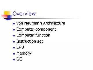
Overview • Part 1 – The Design Space • Integrated Circuits • Levels of Integration • CMOS Circuit Technology • CMOS Transistor Models • Circuits of Switches • Fully Complementary CMOS Circuits • Technology Parameters • Part 2 – Propagation Delay and Timing • Part 3 – Asynchronous Interactions • Part 4 - Programmable Implementation Technologies
Integrated Circuits • Integrated circuit (informally, a “chip”) is a semiconductor crystal (most often silicon) containing the electronic components for the digital gates and storage elements which are interconnected on the chip. • Terminology - Levels of chip integration • SSI (small-scale integrated) - fewer than 10 gates • MSI (medium-scale integrated) - 10 to 100 gates • LSI (large-scale integrated) - 100 to thousands of gates • VLSI (very large-scale integrated) - thousands to 100s of millions of gates
MOS Transistor 0 V olts V V olts 0 V olts n-Channel T ransistor : OFF - no D-to-S Current r DD
Switch Models for MOS Transistors • n-Channel –Normally Open (NO) Switch Contact • p-Channel – Normally Closed (NC) Switch Contact
Circuits of Switch Models • Series • Parallel
Fully-Complementary CMOS Circuit • Circuit structure for fully-complementary CMOS gate
CMOS Circuit Design Example • Find a CMOS gate with the following function: • The switch model circuit for F1 in terms of NC contacts is the dual of the switch model circuit for F0:
CMOS Circuit Design Example • Replacing theswitch modelswith CMOStransistors
Technology Parameters • Specific gate implementation technologies are characterized by the following parameters: • Fan-in – the number of inputs available on a gate • Fan-out – the number of standard loads driven by a gate output • Logic Levels – the signal value ranges for 1 and 0 on the inputs and 1 and 0 on the outputs (see Figure 1-1) • Noise Margin – the maximum external noise voltage superimposed on a normal input value that will not cause an undesirable change in the circuit output • Cost for a gate - a measure of the contribution by the gate to the cost of the integrated circuit • Propagation Delay – The time required for a change in the value of a signal to propagate from an input to an output • Power Dissipation – the amount of power drawn from the power supply and consumed by the gate
Fan-in • For high-speed circuits, fan-in is often restricted on gate primitives to no more than 4 or 5. Fig. 6-4 Implementation of a 7-input NAND Gate
Fan-out • Fan-out can be defined in terms of a standard load • Example: 1 standard load equals the load contributed by the input of 1 inverter. • Transition time -the time required for the gate output to change from H to L, tHL, or from L to H, tLH • increases when load on the output increases • The maximum fan-out that can be driven by a gate is the number of standard loads the gate can drive without exceeding its specified maximumtransition time
Cost • In an integrated circuit: • The cost of a gate is proportional to the chip area occupied by the gate • The gate area is roughly proportional to the number and size of the transistors and the amount of wiring connecting them • Ignoring the wiring area, the gate area is roughly proportional to the gate input count • So gate input count is a rough measure of gate cost • If the actual chip layout area occupied by the gate is known, it is a far more accurate measure
Supplement documents • ICdigital logic families • RTL (Resistor-transistor logic) • DTL (Diode-transistor logic) • TTL (Transistor -transistor logic) • ECL (Emitter-coupled logic) • MOS (Metal-oxide semiconductor) • CMOS (Complementary Metal-oxide semiconductor)
Supplement documents Computing fan-out
Supplement documents Power dissipation
Supplement documents TTL families
名言佳句 • 希臘哲學家 亞里斯多德: 卓越不是單一的舉動,而是習慣。