Download
1 / 25
250 likes | 536 Views
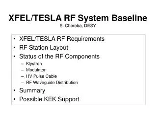
XFEL/TESLA RF System Baseline S. Choroba, DESY. XFEL/TESLA RF Requirements RF Station Layout Status of the RF Components Klystron Modulator HV Pulse Cable RF Waveguide Distribution Summary Possible KEK Support. XFEL/TESLA RF Requirements. Number of sc cavities: 960/21000 total

E N D
XFEL/TESLA RF System BaselineS. Choroba, DESY • XFEL/TESLA RF Requirements • RF Station Layout • Status of the RF Components • Klystron • Modulator • HV Pulse Cable • RF Waveguide Distribution • Summary • Possible KEK Support
XFEL/TESLA RF Requirements Number of sc cavities: 960/21000 total Power per cavity: 122kW/231kW Gradient at 500GeV: 17 .. 23.24MV/m/23.4MV/m Power per 32/36 cavities (4/3 cryo modules): 4.2MW/8.3MW Power per RF station: 5.2MW/9.7MW (including 6% losses in waveguides and circulators and a regulation reserve of 20%/10%) Number of RF stations: 35/572 incl. reserve and injectors Macro beam pulse duration: 950ms RF pulse duration: 1.37ms Repetition rate: 10Hz…50Hz/5Hz Average RF power per station: 250kW (400kW)/120kW
Multi Beam Klystron THALES TH1801 Measured performance Operation Frequency: 1.3GHz Cathode Voltage: 117kV Beam Current: 131A Number of Beams: 7 Cathode loading: 5.5A/cm2 Max. RF Peak Power: 10MW RF Pulse Duration: 1.5ms Repetition Rate: 10Hz RF Average Power: 150kW Efficiency: 65% Gain: 48.2dB Solenoid Power: 6kW Length: 2.5m Lifetime: ~40000h
Multi Beam Klystron THALES TH1801 cont. • 3 klystrons have been manufactured • The prototype PT has been in operation at TTF since May 2000 and has now ca. 19000h operation hours • Series klystron #1 has been returned to the vendor after ca. 3000h (gun arcing) • Series klystron #2 has been tested and returned to the vendor • Gun arcing has been investigated, the problem is identified and the klystron has been modified • Modified klystrons #1 and #2 have been tested at Thales and will be tested at DESY soon. There are no hints of the previous problem anymore. • More klystrons have been ordered and will be delivered in 2005
Multi Beam Klystron CPI VKL-8301 • Design Features: • 6 beams • HOM input and output cavity • Cathode loading: <2.5A/cm2 lifetime prediction: >100000h • Status: • Bakeout in February 2004 • Test at CPI started March 22, 2004
CPI VKL-8301 cont. • MBK has been tested untill June 2004 • has been conditioned to 120kV, 1.7ms, 10Hz in diode mode, excellent beam transmission • achieved 10MW with an efficiency of 60% at an RF pulse length of some 10ms • while increasing the pulse length to some 100ms a window problem occurred at about 4-5MW • the MBK has been removed from test stand and has been opened, the output window has been modified • Retested in Dec./Jan. 2005 • FAT passed Jan. 2005 • test at DESY spring this year
TOSHIBA E3736 MBKin cooperation with KEK • Design Features: • 6 beams • Ring shaped cavities • Cathode loading: <2.1 A/cm2 • Status: • Bakeout April 2004 • Test started for July 2004
Cathode current (red) / collector current (blue) 115kV Cathode voltage (yellow): Output of DC P/S 131 A Cathode current (Green): output of The IGBT switch 1.5ms TOSHIBA E3763 cont. • in August modulator has been upgraded • MBK has been conditioned to 115kV, 1.5ms, 10Hz in diode mode and has excellent beam transmission (>98%)
TOSHIBA E3763 cont. • achieved 8.8MW at 1.3GHz and 9.5MW at 1.296GHz with 20ms and 1Hz • tuning of cavities was required; • the klystron achieved 10.3MW at 40ms, 1Hz (Sept. 04) • achieved: 10.3MW peak in 1ms long pulse at 10Hz (Nov. 04) • Main purpose of this tube: beam transmission test • FAT scheduled for May 2005 115kV Cathode voltage (yellow): Output of DC P/S 131 A RF Output (port A: yelow , Port B: blue) RF drive 1.0ms
Horizontal Klystron • Modification towards a horizontal version is straightforward (no technological risks), but must be done now for the XFEL • Horizontal klystrons are already in use e.g. the LEP klystrons at CERN or the B-factory klytrons at SLAC • One vendor has already designed a horizontal version
Klystron Replacement • the klystron lifetime will be determined by the cathode lifetime since other klystron components are operated at a moderate level • with a klystron lifetime of 40000h and an operation time of 5000h per year 8 klystrons must be replaced during a monthly access day • an overhead of 12 klystrons will be installed, therefore no degradation of accelerator performance is expected between two access days • teams of 3-4 people will exchange a klystron within a few hours; klystrons will be equipped with connectors (HV, controls, cooling, waveguides) which allow fast exchange of a klystron in the tunnel
Modulators • Modulators must generate HV pulses up to 120kV and 140A, 1.57ms pulse length and 5...50Hz repetition rate • The top of the pulse must be flat within 1% • The bouncer type modulator with its simple circuit diagram was chosen for TESLA and the XFEL
The FNAL Modulator Waveforms • 3 modulators have been developed, built and delivered to TTF by FNAL since 1994 • They are continuosly in operation under different operation conditions FNAL Modulator at TTF
Industry made Modulator PPT Modulator HVPS and Pulse Forming Unit • Industry made subunits (PPT, ABB, FUG, Poynting) • Constant power power supply for suppression of 5Hz repetition rate disturbances in the mains • Compact storage capacitor bank with self healing capacitors • IGCT Stack (ABB); 7 IGCTs in series, 2 are redundant IGCT Stack
Industry made Modulator cont. • Low leakage inductance pulse transformer (ABB) L<200mH resulting in shorter HV pulse rise time of <200ms • Light Triggered Thyristor crowbar avoiding mercury of ignitrons Pulse Transformer Klystron Voltage 113kV Klystron Current 132A
Modulator Status • 10 Modulators have been built, 3 by FNAL and 7 by industry • 8 modulators are in operation • 10 years operation experience exists • Many vendors for modulator components are available • Test at rep. rates up to 50Hz, keeping the average power constant • Work towards a more cost efficient, compact, reliabale, modular design must be done now
HV Pulse Cable • Transmission of HV pulses (10kV, 1.6kA, 1.57ms, 5..50Hz) from the pulse generating unit (modulator hall) to the pulse transformer (accelerator tunnel) • Maximum length 2.8km • Impedance of 25 Ohms (4 cable in parallel will give 6.25 Ohms in total) to match the klystron impedance • Triaxial construction (inner conductor at 10kV, middle conductor at 1kV, outer conductor at ground)
HV Pulse Cable cont. diameter 30mm dielectric material: XLPE
HV Pulse Cable cont. Primary Current 1.1kA Klystron Voltage 128kV Primary Voltage 10.6kV
RF Power Waveguide Distribution • Distribution of klystron output power to the superconducting cavities • Protection of the klystron from reflected power • Control of phase and Qext
RF Waveguide Componentsfor operation with air Circulator (Ferrite) 3 Stub Tuner (IHEP, Bejing, China) E and H Bends (Spinner) RF Load (Ferrite) Hybrid Coupler (RFT, Spinner) RF Load (Ferrite)
RF Waveguide Distribution Status • Waveguide components for TESLA and XFEL have been developed in cooperation with industry or are standard of the shelves components • Operation experience of 10 years from TTF • Development of integrated components has been started (e.g. circulator with integrated load) and must be continued • Development of a high power circulator for operation with air and development of new tuners have been started
Summary • All main components for the XFEL RF system are available today • The HV pulse cable prototype has been manufactured and test has been started • For all components at least two vendors are available and many components are standard catalog products • Improvements for more cost efficient, enhanced reliable and modular components must be done now • Detailed layouts of all components for the XFEL are required now.
Possible KEK support • Continue support of Toshiba MBK development (YongHo Chin, KEK) • Accompany development of japanese bouncer modulator ( e.g. visit of H. Matsumoto, KEK and Choroba at Nichicon in Kusatsu in Nov. 04) • Support to qualify japanese waveguide component vendors (Nihon Koshuha?)