Chapter 8 Feedback
Chapter 8 Feedback . Introduction 8.1 The general feedback structure 8.2 Some properties of negative feedback 8.3 The four basic feedback topologies 8.4 The series-shunt feedback amplifier 8.5 The series-series feedback amplifier 8.6 The shunt-shunt and shunt-series feedback amplifier

Chapter 8 Feedback
E N D
Presentation Transcript
Chapter 8 Feedback Introduction 8.1 The general feedback structure 8.2 Some properties of negative feedback 8.3 The four basic feedback topologies 8.4 The series-shunt feedback amplifier 8.5 The series-series feedback amplifier 8.6 The shunt-shunt and shunt-series feedback amplifier 8.10 Stability study using bode plot 8.11 Frequency compensation
It’s impossible to think of electronic circuits without some forms of feedback. Negative feedback Desensitize the gain Reduce nonlinear distortion Reduce the effect of noise Control the input and output impedance Extend the bandwidth of the amplifier The basic idea of negative feedback is to trade off between gain and other desirable properties. Positive feedback will cause the amplifier oscillation. Introduction
PartI: The basic concept and some Properties of negative feedback PartII: The four basic feedback and analysis PartIII: The loop gain, stability problem and frequency compensation Three Parts:
PartI The basic concept Judgment and Properties of feedback examples
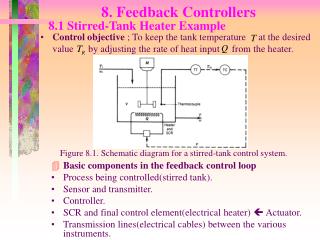
PartI: The basic concept and some Properties of negative feedback 8.1 The General Feedback Structure This is a signal-flow diagram, and the quantities x represent either voltage or current signals. In electronic circuits, part of or all output signal is fed back to input, and affects the input signal value, which is called feedback.
Negative feedback and positive feedback: According to the effecting of feedback 1) positive feedback increases the signal that appears at the input of the basic amplifier 2) negative feedback reduces the signal that appears at the input of the basic amplifier • DC feedback and AC feedback: • Feedback quantity only contains DC quantity,is called DC • feedback • 2) Feedback quantity only contains AC quantity,is called AC • feedback • Usually AC feedback and DC feedback are concomitant
The feedback judgment: • No feedback • Feedback exists • No feedback
The judgment of feedback parity Instantaneous polarity method: 1) Regulate the polarity of input signal relative to ground at sometime. 2) Decide all points’ parity step by step, at last get the parity of output signal. 3) According to the parity of output signal decides the parity of amount of feedback. 4) If amount of feedbackincreases the signal that appears at the input of the basic amplifier, the circuit inducts the positive feedback. Otherwise, it inducts the negative feedback.
To integrated operational amplifiers,the input quantity can be UD or iN(iP)
To discrete components amplifiers,the input quantity can be Ube or ib
The judgment of DC feedback and AC feedback DC feedback,no AC feedback AC feedback,no DC feedback
Example :feedback?Positive or negative?DC or AC? AC and DC negative feedback
The General Feedback Equation • Open loop gain A • Feedback factor β • Loop gain Aβ • Closed loop gain Af • Amount of feedback (1+ Aβ)
The General Feedback Equation • If Aβ >>1, The gain of the feedback amplifier is almost entirely determined by the feedback network. • If Aβ >>1, which implies that the signal Xi at the input of the basic amplifier is reduced to almost zero.
Gain desensitivity 8.2 Some Properties of Negative Feedback the percentage change in Af (due to variations in some circuit parameter) is smaller than the percentage change in A by the amount of feedback. For this reason the amount of feedback, 1 + Aβ, is also known as the desensitivity factor.
2. Bandwidth extension Some Properties of Negative Feedback Note that the amplifier bandwidth is increased by the same factor by which its midband gain is decreased, maintaining the gain-bandwidth product at a constant value.
3. Noise reduction Some Properties of Negative Feedback
Some Properties of Negative Feedback 4. Reduction in nonlinear distortion
Some Properties of Negative Feedback 4. Reduction in nonlinear distortion
May 11th, 2008 8.1; 8.7; Homework:
Voltage amplifier---series-shunt feedback voltage mixing and voltage sampling 8.3 The Four Basic Feedback Topologies
Current amplifier---shunt-series feedback Current mixing and current sampling The Four Basic Feedback Topologies
Example: Figure 8.5 A transistor amplifier with shunt–series feedback. (Biasing not shown.)
Transconductance amplifier---series-series feedback Voltage mixing and current sampling The Four Basic Feedback Topologies
Example: Figure 8.6 An example of the series–series feedback topology. (Biasing not shown.)
Transresistance amplifier---shunt-shunt feedback Current mixing and voltage sampling The Four Basic Feedback Topologies
Example: Figure 8.7 (a) The inverting op-amp configuration redrawn as (b) an example of shunt–shunt feedback.
May 11nd, 2008 8.14; 8.15; 8.17; 8.19 Homework:
The ideal situation The practical situation Summary 8.4 The Series-Shunt Feedback Amplifier
The Ideal Situation • A unilateral open-loop amplifier (A circuit). • An ideal voltage mixing voltage sampling feedback network (β circuit). • Assumption that the source and load resistance have been included inside the A circuit.
The Ideal Situation Equivalent circuit. Rif and Rof denote the input and output resistance with feedback.
Input resistance In this case, the negative feedback increases the input resistance by a factor equal to the amount of feedback. Output resistance In this case, the negative feedback reduces the output resistance by a factor equal to the amount of feedback. Input and Output Resistance with Feedback
The Practical Situation • Block diagram of a practical series–shunt feedback amplifier. • Feedback network is not ideal and load the basic amplifier thus affect the values of gain, input resistance and output resistance.
The Practical Situation The circuit in (a) with the feedback network represented by its h parameters. Omit the controlled source h21I1
The Practical Situation The circuit in (b) with h21 neglected.
The load effect of the feedback network on the basic amplifier is represented by the components h11 and h22. The loading effect is found by looking into the appropriate port of the feedback network while the port is open-circuit or short-circuit so as to destroy the feedback. If the connection is a shunt one, short-circuit the port. If the connection is a series one, open-circuit the port. Determine the β. The Practical Situation
Ri and Ro are the input and output resistances, respectively, of the A circuit. Rif and Rof are the input and output resistances, respectively, of the feedback amplifier, including Rs and RL. The actual input and output resistances exclude Rs and RL. Summary
Op amplifier connected in noninverting configuration with the open-loop gain μ, Rid and ro Find expression for A, β, the closed-loop gain Vo/Vi , the input resistance Rinand the output resistance Rout Find numerical values Example of Series-Shunt Feedback Amplifier
The ideal situation The practical situation Summary 8.5 The Series-Series Feedback Amplifier
The Ideal Situation Transconductance gain
The Ideal Situation Tranresistance feedback factor
Input resistance In this case, the negative feedback increases the input resistance by a factor equal to the amount of feedback. Output resistance In this case, the negative feedback increases the output resistance by a factor equal to the amount of feedback. Input and Output Resistance with Feedback
The Practical Situation Block diagram of a practical series–series feedback amplifier. Feedback network is not ideal and load the basic amplifier thus affect the values of gain, input resistance and output resistance.
The Practical Situation The circuit of (a) with the feedback network represented by its z parameters.