Image Motion
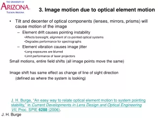
Image Motion. Stephen Smee smee@jhu.edu (410) 516-7097. Instrument Flexure. Goals Determine the image motion and defocue under a 1g load for a 15 deg. rotation of the rotator Modeling strategy Model vessel flexure, dewar sag, and camera module sag


Image Motion
E N D
Presentation Transcript
Image Motion Stephen Smee smee@jhu.edu (410) 516-7097
Instrument Flexure • Goals • Determine the image motion and defocue under a 1g load for a 15 deg. rotation of the rotator • Modeling strategy • Model vessel flexure, dewar sag, and camera module sag • Image motion due to camera module sag is 1.3:1 • Image motion due to vessel flexure and dewar sag is 1:1 • Defocus results from detector tilt and motion along the optical axis • Superimpose results to calculate image shift and defocus 2
Image Motion • Image motion results from flexure in the camera module mount and motion of the detector Apply gravity to vessel and dewar Apply gravity to CM Zero Gravity 1g 1g dCM dDet The red dot is a star, the crosshair is fixed to the detector array Image motion = dCM - dDet 3
Vessel Flexure Model • Half-symmetric model • Vessel divided into eight segments • Density of each section adjusted to represent internal components • CG of simplified model matches quite well to actual model • 1842 lb astatic vertical load applied to load ring • 1g load applied to entire vessel • Fixed boundary condition at the conical adapter 4
Vessel Flexure Results • Dewar Support Ring motion • Full Dewar • Decenter: 13.5 mm • Tilt: 0.8 mm top-to-bottom across the detector • Empty Dewar • Decenter: 4 mm • Tilt: 0.1 mm top-to-bottom across the detector Dewar Support Ring 5
Gravity Loading Dewar: 55 lbs LN2: 25.8 lbs Detector: 7.6 lbs Filter wheel: 15.5 lbs Flattener wheel: 9.5 lbs Detent assembly: 2.3 lbs Total 115.7 lbs Moment Loading Filter wheel: 62.2 in∙lbs Flattener wheel: 26.13 in∙lbs Detector: 10.8 in∙lbs Detent assembly: 5.6 in∙lbs Dewar Flexure Model g 6
Dewar Motion Full Dewar Decenter: 16 mm Tilt: 0.3 mm top-to-bottom across the detector Empty Dewar Decenter: 13 mm Tilt: 0.4 mm top-to-bottom across the detector 1g Dewar Flexure Results 7
Flexure Model Boundary Conditions (3X) Fixed Boundary Condition Loading Tied interface between the support pin and the titanium flexure Gravity loading applied to all elements 300K * 200K * CM load applied to this face (86 lbs) * Note: Temperature and the resulting radial contraction was included in the model 8
Flexure Results 1g Loading • Image motion due to motion of the CM support ring is 1.3:1. Therefore the image motion due to a 1g load is 0.0013” or 33 um. • Tilt is negligible and image motion is insensitive to tilt Ring center sags 0.0010” U1 9
Flexure Results Summary • 1g decenter of detector • Full dewars: dDet = 29.5 mm • Empty dewars: dDet = 17 mm • 1g image motion due to camera module sag • dCM = 33 mm • 1g image motion • Full dewars: 3.5 mm • Empty dewars:16 mm • Image motion over a 15 deg rotation • Full dewars: 0.9 mm (< 1/3 pixel) • Empty dewars: 4.2 mm ( < 1/3 pixel) • Defocus is well within the ± 30 mm diffraction limited DOF 10