DCLL TBM Design Summary and Future Activities
150 likes | 173 Views
Dive into the current activities and future design options of the DCLL TBM. Explore structural and thermal analysis, equatorial port plug assembly, and important design changes. Find out about the FEA completed work and the planned activities to enhance the TBM design for optimal performance.

DCLL TBM Design Summary and Future Activities
E N D
Presentation Transcript
DCLL TBM DesignStatus, Current and future activities Mo Dagher and The DCLL Team FNST Meeting, UCLA Aug 18th , 2009
Outline DCLL design summary Current activities. Structural and thermal analysis Future Design options and changes.
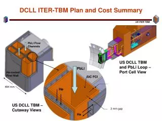
Equatorial Port Plug Assembly DCLL TBM Equatorial Port Plug Frame Assembly DCLL TBM Assembly Shielding* Vacuum Boundary Back Plate* * Shielding and Pipe penetrations shown in this view are not representative of the final design. Additional design work is under way to complete this assembly.
TBM Assembly, General Configuration PbLi Outlet Line PbLi Inlet Line Shear keys He Outlet Line Electric Strap He Inlet Line Flexible Support Points PbLi Drain Line
TBM Assembly Exploded View Major Components
DCLL TBM Assembly Mid Plane Section PbLi Outlet Channels (3) Inner He Distribution Manifold (Circuit 1) PbLi Inlet Channels (3) Divider Plate Plenum Outer He Distribution Manifold (Circuit 2) First Wall Grid Plates Grid Plate He Outlet Plenum Inner He Dist. Manifold (Circuit 2) He Outlet Plenum Grid He Inlet Plenum Outer He Distribution Manifold (Circuit 1) Back Plate
Flow through top plate He Flow Scheme First part of the HE flow is through the Bottom Plate, FW and the TOP Plate. FW flow is divided into two flow circuits with counter flow configuration. Each flow circuit is also divided into seven passes. The goal of this flow scheme is to achieve a uniform flow and temperature distribution across the FW. Second part of the He flow through the grid and divider plates in order to maintain a low structure temperature. Flow through First Wall
PbLi Flow Scheme 5) LL flow exits TBM 1) LL Flow Enters TBM 2)LL flow splits into Three Channels and flows down inner chamber 4) LL flow Collected in the Upper Manifold 3) LL flow turns around and flows up outer chamber
FEA: Completed Work • Thermo-structural analysis was performed on the entire TBM structure under various, simplifiedloading combinations: • Normal pressurization (8 MPa He, 0.5 MPaPbLi) at 20 ºC and 450 ºC • LOCA pressurization (8 MPa He and PbLi) at 20 ºC and 450 ºC • Different structural boundary conditions were applied on the back plate in an effort to investigate different support systems. Contour plot showing displacement magnitude (in meters) of the TBM, with central support option, under normal pressurization at 450 ºC. Central fixture applied in blue region. Maximum displacement magnitude is 5.735 mm.
TBM Design Future activities The TBM support system is not fully designed yet pending further analysis. Most importantly structural analysis that includes the Disruption loads. Flexible Support Points
Flow through top plate FW He flow profile He Velocity profile through FW using Cradle, courtesy of Alice Ying. This profile shows a large variation in the flow distribution between individual channels. Flow variation are consistent among the central five passes. Design changes should be implemented in the side manifolds to provide even flow distribution into the FW channels Flow through First Wall
TBM Design Future activities The next design iteration of the DCLL TBM will be based on input from various analysis results and experiments. He Inlet and side manifold redesign will be required to insure proper flow distribution in the First Wall and the Top and Bottom plates. 2. Next will be to evaluate the He flow inside the Grid and divider plates. Look at the flow distribution and make design adjustments 3. The last item of the He flow circuit is the back plate inlet and outlet manifolds. Final design will be based on flow distribution in the FW and the grid plates.
TBM Design Future activities The current FCI design exhibits high thermal stresses. An alternative design would be to use the nested FCI design concept based on work done by Sergey and Siegfried.
TBM Design Future activities Finally all pipe connections between the TBM and the AEU must be evaluated based on the analysis results showing displacement magnitudes, so proper joints are implemented at the TBM, the Vacuum boundary and the AEU Interface Joint No 2 Inter-space Pipe Assembly – TBM Frame Assy Interface Joint No 3 Bio-Shield Pipe Penetration – AEU Pipe Connection Interface Joint No 1 TBM - Shielding