MHD related activities for DCLL
230 likes | 378 Views
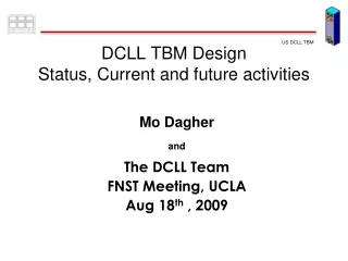
MHD related activities for DCLL. Presented by Sergey Smolentsev , UCLA. FNST MEEETING August 18-20, 2009 Rice Room, 6764 Boelter Hall, UCLA. LAYOUT. Assessment of DCLL IB DEMO blanket SiC-PbLi slip phenomena Status of “ mixed convection ” studies

MHD related activities for DCLL
E N D
Presentation Transcript
MHD related activities for DCLL Presented by Sergey Smolentsev, UCLA FNST MEEETING August 18-20, 2009 Rice Room, 6764 Boelter Hall, UCLA
LAYOUT • Assessment of DCLL IB DEMO blanket • SiC-PbLi slip phenomena • Status of “mixed convection” studies • Status of “corrosion” code development • Modeling Chinese “FCI” experiment • “Corrosion” experiment with SiC in Riga and related activities
Sketch of the IB DEMO blanket. Only 3 lower modules are shown. (a) Front view, including the blanket modules, He and PbLi access ducts, vacuum vessel, and the TF coil. (b) Rear view. Only the PbLi carrying elements and the TF coil are shown. (c) He and PbLi access ducts. (d) PbLi access ducts. Assessment of DCLL IB blanket, 1 Principal DCLL DEMO IB blanket design with He and PbLi access pipes • IB versus OB DEMO blanket: • smaller available space • lower heat load (the average • neutron wall load is 1.33 MW/m2) • long poloidal path of the PbLi • flows (~2-4 m) • significantly higher magnetic • field (10-12 T against 4-6 T) Main focus:How high is the MHD pressure drop? • Analysis: • 3D MHD pressure drop • Effect of FCI on p2D in poloidal flows • Flow in the access ducts S. Smolentsev, C. Wong, S. Malang, M. Dagher, M. Abdou, MHD Considerations for the DCLL Inboard Blanket, ISFNT-9, Dalian, China, 2009.
Inlet/outlet manifold Flow in a fringing field Assessment of DCLL IB blanket, 2 Summary of 3D MHD pressure drop • Average NWL: 1.33 MW/m2 • Magnetic field: 10 T • PbLi Tin/Tout=450/750C • Velocity in a blanket duct: 0.015 m/s • Each module: 1.4x1.4x0.5 m • 12 poloidal ducts per module, 0.2x0.2 m • The longest access duct is 4.2 m • 5 mm SiC FCI Total MHD pressure drop = 1.43 MPa < 2 MPa (providing ~1-10 S/m)
Effectiveness of the 5 mm SiC FCI as electric insulator in the poloidal IB blanket flow in a 10 T magnetic field (Ha=26500). Assessment of DCLL IB blanket, 3 Effect of FCI electrical conductivity on MHD pressure drop in poloidal flows • <0.1 S/m - ideal insulation • ~1 S/m - p2D~10-3 MPa • ~10 S/m - p2D~10-2 MPa • ~100 S/m - p2D~10-1 MPa • ~1000 S/m - p2D~1 MPa • If ~100 S/m, p2D~ p3D Ideal insulation Our goal is to have p2D<< p3D. Therefore, <100 S/m is required (<1-10 S/m is desired)
(a) (b) Sketch of the cross-section of the PbLi access duct (a) and the computational mesh (b). Assessment of DCLL IB blanket, 4 Flow in the access ducts “cold” PbLi flow in: annulus “hot” PbLi flow out: inner duct
Assessment of DCLL IB blanket, 5 Flow in the access ducts • No flow occurs in the • sections of the annulus • perpendicular to B • This may cause lack of • cooling of the inner duct • Pipe-in-pipe geometry • looks attractive • Turbulence (if appears) • will likely result in better • cooling B=4 T, =0 B=4 T, =10 S/m More studies for access ducts needed
Assessment of DCLL IB blanket, 6 CONCLUSIONS • The total MHD pressure drop is 1.43 MPa (30%) • We are approaching the limit of 2 MPa. Special care should be taken in case of any design modifications • <100 S/m (5 mm FCI) is required, <1-10 S/m is desired • Flows in access ducts need more analysis (including possible turbulence effects) as the present studies suggest lack of cooling. Pipe-in-pipe configuration seems to be the best option
SiC-PbLi slip phenomena, 1 • Recent studies suggest that SiC is not fully wetted by PbLi Pint, B.A., More, K.L., Meyer, H.M., Distefano, J.R.: Recent progress addressing compatibility issues relevant to fusion environments, Fusion Science and Technology, 47, 851-855 (2005) Morley, N.B., Medina, A., Abdou, M.A.: Measurements of specific electrical contact resistance between SiC and lead-lithium eutectic alloy, TOFE 18, San Francisco, Sep. 28 – Oct. 2, Book of Abstracts, P2.66, (2008) Changho, P., Kazuyuki, N., Yamamoto, Y., Konishi, S.: Compatibility of materials for advanced blanket with liquid LiPb, TOFE 18, San Francisco, Sep. 28 – Oct. 2, Book of Abstracts, P1.67 (2008) • Poor wetting is direct indication of slip phenomena • We use a parameter called “slip length” to include the slip effect in MHD/HT models CORROSION OF SILICON CARBIDE FILTER IN MOLTEN METAL K. Sujirote and K. Goyadoolya National Metal and Materials Technology Center Science Park, Pathumthani 12120 Thailand “Due to its non-wetting behavior, and excellent resistance to corrosion and thermal shock, corrugated silicon carbide filter is suitable for filtering molten metal.”
SiC-PbLi slip phenomena, 2 Characterization of slip effect on MHD flow • The slip effect can affect blanket flows in two ways: • Reduction of MHD pressure drop – definitely a useful tendency • More unstable flows –effect on heat and mass transfer; not fully understood yet Slip length increases S. Smolentsev, MHD duct flows under hydrodynamic “slip” condition, Theor. Comput. Fluid Dyn., published online May 19, 2009.
SiC-PbLi slip phenomena, 3 Reduction of MHD pressure drop The slip length can vary from nanometers to microns or even tens of microns for specially designed superhydrophobic surfaces. Assumption: the slip length is 1 m OB: MHD pressure drop reduction: 2 times IB: MHD pressure drop reduction: 3 times Assumption: the slip length is 10 m OB: MHD pressure drop reduction: 10 times IB: MHD pressure drop reduction: 20 times Along with electrical insulation, utilization of slip effect between SiC and PbLi could be considered as another approach to control the MHD pressure drop in DCLL. Example: =100 S/m superhydrophobic FCI is equivalent to =10 S/m no-slip FCI Q:Can we engineer SiC superhydrophobic surfaces? Superhydrophobic bio-fiber surfaces via tailored grafting architecture by Daniel Nystrom, et al, Chem. Commun., 2006, 3594–3596
Inert gas PbLi droplet Heated SiC substrate SiC-PbLi slip phenomena, 4 Steps towards development of SiC-based superhydrophobic surfaces Suggested experiment to demonstrate that slip effect does exist by measuring the contact angle • Simple demonstration experiments for PbLi-SiC • Flow-involving experiments to • confirm directly the interfacial • slip and quantify the slip length • Understanding the interfacial slip • mechanisms • More detailed modeling of the • effect of interfacial slip on MHD flows / HT in blanket conditions • 5. Development and testing SiC-based superhydrophobic surfaces Principal scheme
SiC-PbLi slip phenomena, 5 CONCLUSIONS • A strong effect of the interfacial slip on MHD flows (and also as a consequence, on heat and mass transfer) can be predicted • Providing the slip length is of order of microns, the reduction of MHD pressure drop can be as high as ~10-20 times • Engineering and utilizing superhydrophobic SiC surfaces in DCLL might be an effective approach (along with development of simple electrical insulation) to control the MHD pressure drop • Further analysis on qualification of slip effect on heat and mass transfer is needed
Status of “mixed convection” studies Linear stability analysis and non-linear numerical simulations demonstrate very rich physics. We have significantly advanced recently in understanding mixed convection phenomenon in DCLL blanket conditions. Pre-experimental analysis has been accomplished showing that major mixed convection effects can be simulated in lab conditions. Preparation to the mixed convection experiment is in progress.
Status of “corrosion” code development There are three steps envisaged in the modelling effort for the compatibility of the ferritic/martensitic steels with the eutectic lead-lithium alloy in a fusion blanket system • Relatively simple and easy-to-use code, limited to the analysis of the transport of wall material from the wall/LM interface into the flowing liquid metal for canonical flow geometries and relatively simple flow conditions. This is where we are now 2. Conversion of this code into a subroutine to be used in an available code describing MHD, heat transport, turbulence, buoyancy flow …. under the conditions of a fusion blanket (HIMAG). 3. Use of the experience gained with these codes in a new comprehensive code system to be developed for the prediction of the integral behaviour of a liquid metal fusion blanket.
Picture of experimental MHD facilities in the Southerstern Institute of Physics (SWIP), China. Modeling Chinese “FCI” experiment, 1 We have unofficial collaboration with the MHD group in China lead by Prof. Zengyu Xu Accepted for publication in Magnetohydrodynamics, 2009
Modeling Chinese “FCI” experiment, 2 • 2 mm FCI made of epoxy provides ideal electrical insulation • Maximum magnetic field is 2 T (Ha=2400) • Uniform B-field: 740 mm (length) x 170 mm (width) x 80 mm (height) • Outer SS rectangular duct: 1500 mm long • FCI box: 1000 mm long • Pressure equalization openings: slot (PES) or holes (PES) • Measurements: pressure drop, velocity (LEVI) Modeling was performed under the experimental conditions using the fully developed flow model
Modeling Chinese “FCI” experiment, 3 • Experiment shows significant • decrease in the MHD pressure drop • by FCI • Experiment also demonstrates • better pressure drop reduction in • the PEH case compared to the PES • The computations show much more • pressure drop reduction compared • to the experiment How to explain the difference between the experiment and theory? Prof. Xu: The flow is fully developed but the openings result in extra currents leading to extra high flow opposing force Sergey: There is no way the opening can cause such strong currents but the flow is developing
Modeling Chinese “FCI” experiment, 4 • Modeling confirms that there is a • current loop associated with the • pressure equalization opening but • the current is too small to cause • such a high MHD pressure drop • The pressure drop includes • p3D(due to fringing magnetic field) and p2D. It appears that in the experiment, p3D~ p2D. • Recommendation (experiment): • to measure pressure drop in the • bulk (not in the gap) • (2) to have more measurements of electric potential • Recommendation (modeling): • (1) to perform computations in 3D
A picture of the PbLi loop with auxiliary equipment in the Institute of Physics in Riga, Latvia. “Corrosion” experiment with SiC in Riga and related activities, 1 • Starting from the last summer • we have intensive discussions • with the Institute of Physics in • Riga, Latvia (O.Lielausis, • A.Shishko) on a joint • research on SiC FCI in PbLi in • a strong magnetic field • Other interested people: Prof. • Rene Moreau (France) and • material people from Grenoble • Plan: Latvia – experiment, • UCLA – modeling, • Prof. Moreau – development of • a mathematical model • Although all parties are • technically ready to start, • Latvian group looks for about • 50 K a year for this experiment
f1 stainless steel SiC Bo Z Pb17Li 316L Y f2 Cross-section of the test-section with the SiC plate “Corrosion” experiment with SiC in Riga and related activities, 2 The main goal is to address MHD/corrosion phenomena when a SiC sample is washed by a flowing PbLi in the presence of a strong magnetic field. • Outer duct: SS, 180 mm x 40 mm x 20 mm , 1.5 mm thick. • SiC plate: 100 mm x 40 mm. The thickness is 2 to 5 mm. • The SiC sample is fixed using 10 rectangular brackets (shown in red) made of non-magnetic steel AISI 316 L. • PbLi velocity: 5 cm/s. • Magnetic field: 5 T. • Nominal temperature of PbLi: 550C. • Duration of the experiment: 500 hours. • Bulk velocity is controlled by measuring the electric • potential difference. Pressure drop is measured over the • whole length of the test-section. • In the end of the experiment the SiC sample and all 10 • brackets will be extracted and carefully weighted. An • additional microscopic analysis can be performed either in • Latvia, France or US.
B=0 B=1.8 T “Corrosion” experiment with SiC in Riga and related activities, 3 Similar experiments on corrosion of FS in PbLi in Riga Corrosion rate for samples with and without a magnetic field Macrostructure of the washed samples after contact with the PbLi flow From: F. Muktepavela et al. EXPERIMENTAL STUDIES OF THE STRONG MAGNETIC FIELD ACTION ON THE CORROSION OF RAFM STEELS IN Pb17Li MELT FLOWS, PAMIR 7, 2008 • Strong experimental evidence of significant effect of the applied magnetic field on corrosion rate.
“Corrosion” experiment with SiC in Riga and related activities, 4 • Summary of the observations made with the Grenoble SEM (Scanning Electronic Microscope) and with optical microscopes (July 21, 2009). • The main effect is an erosion of the wall • The eroded material is transported by the • fluid flow without any re-deposition • The grooves in the eroded wall seem to • be a footprint of periodic rolls that appear • due to instability of Hartmann layers. • Some irregularities are also present due • to 3D disturbances in the flow. • The key mechanism might be coupling • between the hydrodynamic instability • (responsible for the rolls) and chemical • dissolution of the wall material (probably • related to an electro-migration effect). Yves Bréchet, René Moreau and Laurent Maniguet