Download
1 / 15
150 likes | 168 Views
Learn about shearing stresses in beams and thin-walled members, including determination methods and stress distribution discussions. Explore practical examples and solutions to understand longitudinal shear, unsymmetric loading, and transverse loading effects. Gain insights into the importance of shear flow and equilibrium in beam elements.

E N D
6 Shearing Stresses in Beams and Thin-Walled Members
Shearing Stresses in Beams and Thin-Walled Members Introduction Shear on the Horizontal Face of a Beam Element Example 6.01 Determination of the Shearing Stress in a Beam Shearing Stresses txy in Common Types of Beams Further Discussion of the Distribution of Stresses in a ... Sample Problem 6.2 Longitudinal Shear on a Beam Element of Arbitrary Shape Example 6.04 Shearing Stresses in Thin-Walled Members Plastic Deformations Sample Problem 6.3 Unsymmetric Loading of Thin-Walled Members Example 6.05 Example 6.06
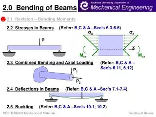
Transverse loading applied to a beam results in normal and shearing stresses in transverse sections. • Distribution of normal and shearing stresses satisfies • When shearing stresses are exerted on the vertical faces of an element, equal stresses must be exerted on the horizontal faces Introduction • Longitudinal shearing stresses must exist in any member subjected to transverse loading.
For equilibrium of beam element • Note, • Substituting, Shear on the Horizontal Face of a Beam Element • Consider prismatic beam
Shear flow, • where • Same result found for lower area Shear on the Horizontal Face of a Beam Element
Example 6.01 • SOLUTION: • Determine the horizontal force per unit length or shear flow q on the lower surface of the upper plank. • Calculate the corresponding shear force in each nail. A beam is made of three planks, nailed together. Knowing that the spacing between nails is 25 mm and that the vertical shear in the beam is V = 500 N, determine the shear force in each nail.
SOLUTION: • Determine the horizontal force per unit length or shear flow q on the lower surface of the upper plank. • Calculate the corresponding shear force in each nail for a nail spacing of 25 mm. Example 6.01
The average shearing stress on the horizontal face of the element is obtained by dividing the shearing force on the element by the area of the face. • On the upper and lower surfaces of the beam, tyx= 0. It follows that txy= 0 on the upper and lower edges of the transverse sections. Determination of the Shearing Stress in a Beam • If the width of the beam is comparable or large relative to its depth, the shearing stresses at D1 and D2 are significantly higher than at D.
For a narrow rectangular beam, • For American Standard (S-beam) and wide-flange (W-beam) beams Shearing Stresses txyin Common Types of Beams
Consider a narrow rectangular cantilever beam subjected to load P at its free end: • From Saint-Venant’s principle, effects of the load application mode are negligible except in immediate vicinity of load application points. • Stress/strain deviations for distributed loads are negligible for typical beam sections of interest. Further Discussion of the Distribution of Stresses in a Narrow Rectangular Beam • Shearing stresses are independent of the distance from the point of application of the load. • Normal strains and normal stresses are unaffected by the shearing stresses.
Sample Problem 6.2 • SOLUTION: • Develop shear and bending moment diagrams. Identify the maximums. • Determine the beam depth based on allowable normal stress. A timber beam is to support the three concentrated loads shown. Knowing that for the grade of timber used, • Determine the beam depth based on allowable shear stress. • Required beam depth is equal to the larger of the two depths found. determine the minimum required depth d of the beam.
Sample Problem 6.2 SOLUTION: Develop shear and bending moment diagrams. Identify the maximums.
Determine the beam depth based on allowable normal stress. Sample Problem 6.2 Check for shearing stress:
Determine the beam depth based on allowable shear stress. • Required beam depth is equal to the larger of the two.
Consider prismatic beam with an element defined by the curved surface CDD’C’. • Except for the differences in integration areas, this is the same result obtained before which led to Longitudinal Shear on a Beam Element of Arbitrary Shape • We have examined the distribution of the vertical components txy on a transverse section of a beam. We now wish to consider the horizontal components txz of the stresses.