Download
1 / 72
910 likes | 1.55k Views
COE 341: Data & Computer Communications (T061) Dr. Radwan E. Abdel-Aal. Chapter 8: Multiplexing. Where are we:. Chapter 7: Data Link: Flow and Error control. Data Link. Chapter 8: Improved utilization: Multiplexing. Physical Layer.

E N D
COE 341: Data & Computer Communications (T061)Dr. Radwan E. Abdel-Aal Chapter 8: Multiplexing
Where are we: Chapter 7: Data Link: Flow and Error control Data Link Chapter 8: Improved utilization: Multiplexing Physical Layer Chapter 6: Data Communication: Synchronization, Error detection and correction Chapter 4: Transmission Media Transmission Medium Chapter 5: Encoding: From data to signals Chapter 3: Signals and their transmission over media, Impairments
Contents • Introduction • Two Multiplexing Techniques • FDM • TDM • Synchronous • Statistical • Application: ADSL (Asymmetric Digital Subscriber Line)
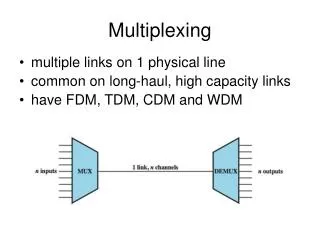
Introduction • Multiplexing: A generic term used when more than one application or source share the capacity of one link • Objective is to achieve better utilization of the link bandwidth (channel capacity) Multiplexer Demultiplexer
Motivation • High capacity (data rate) links are cost effective. i.e. it is more economical to go for large capacity links • But requirements of individual users are usually fairly modest…e.g. 9.6 to 64 kbps for non intensive (graphics, video applications). • Solution: Let a number of such users share the high capacity channel (Multiplexing) • Example: Long haul trunk traffic: • High capacity links: Optical fiber, terrestrial microwaves, etc. • Large number of channels between cities over large distances
Multiplexing Types • Our three resources: Space Time Frequency • Our channels must be separated in at least one resource (can overlap in the other two) • The resource in which they are separated is “divided” between them: • SDM: Separation in space • TDM: Separation in time • FDM: Separation in frequency Space Frequency Time FDM: Frequency Division Multiplexing TDM: Time Division Multiplexing To use the same circuit (line) i.e. sharing space: Use either TDM or FDM
Multiplexing Types Modulation Or shift keying Encoding Representing digital or analog data Analog Signals Digital Signals Separation in Frequency Separation in time by interleaving FDM: Frequency Division Multiplexing TDM: Time Division Multiplexing WDM: Wavelength Division Multiplexing (a form of FDM) Synchronous Statistical
Frequency Division Multiplexing (FDM) • Channels exist on the same line (space) at the same time: • Must be separated in frequency! f t
FDM • Useful bandwidth of medium exceeds required bandwidth of channel • Signal of each channel is modulated on a different carrier frequency fc • So, channels are shifted from same base band by different fc’s to occupy different frequency bands • Carrier frequencies separated so that channels do not overlap (also include some guard bands) • Disadvantage: Channel spectrum is allocated even if no data available for transmission in channel (rigid allocation)
FDM Same time Different Frequencies
FDM Multiplexing Process: Time-Domain View at TX Qty: 3 Fc (Different for each channel) Modulator
FDM Multiplexing Process: Frequency-Domain View at TX 0 4 KHz f2 f1 f3 f1 f f f2 f3 All source channels are at (same) base band Restoration at RX: 3 different pass-band filters, each bracketing a channel
FDM De-Multiplexing Process: Time-Domain View at RX Filter pass bands f1 f2 f3 Demultiplexing Filters Low Pass Filter fc Demodulator (Different for each channel Same as those used at TX) Qty: 3 Qty: 3
FDM De-Multiplexing Process: Frequency-Domain View at RX • Guard bands prevent channel overlap • But represent wasted • spectrum f1 f f2 0 4 KHz f3 All received channels restored to base band
FDM System – Transmitter Subcarriers To meet Transmission Requirements Main Carrier Any type of modulation: AM, FM, PM Group of channels Individual base band channels
FDM System – Receiver f1 f2 Subcarriers fc Main Carrier f3 Composite base band signal mb(t) recovered Individual base band channels recovered
FDM of Three Voice band Signals Guard bands To reduce channel spectrum overlap BW, allocated: 0 – 4000 Hz BW, actual : 300 – 3400 Hz Assume we will keep only the lower side band for each channel fc What is the modulation type ? 3 MUXed channel Using lower side band only 3 Subcarriers at: 64, 68, and 72 KHz Channel overlap means crosstalk!
Analog Carrier Systems One-go Vs Hierarchical: …. Master super group Stages …. Super group …. …. Group Channel …. ... …. ... 4000 channels 4000 channels • Modular approach • Easier to implement • Also, not all channels may be available • at one place
Analog Carrier Systems Each channel is 300 to 3400 = 3100 Hz. 4000 Hz provides 900 Hz guard band • Devised by AT&T (USA) • Hierarchy of FDM schemes: MUXing in stages • Group: AM, Lower Side band • 12 voice channels = 12 x 4 kHz = 48 kHz BW • 12 sub carriers: 64 kHz – 108 kHz in 4 KHz intervals • Frequency range for group: 60 kHz – 108 kHz = 48 kHz (lower side band) • Super group: FM • 5 groups = 5 x 48 kHz = 240 kHz BW • 5 sub carriers: 420 kHz - 612 kHz at 48 KHz intervals (No GBs bet. groups) • Frequency range: 312 kHz – 552 kHz = 240 kHz • Master group: FM • 10 super groups = 10 x 240 kHz = 2400 kHz BW • 10 sub carriers: 1116 kHz - 3396 kHz (Min of 8 KHz GBs between SGs) • BW of 2.52 MHz (> 10 x 240 KHz = 2.4 MHz due to GB between SGs) • Jumbo group: FM • 6 master groups • i.e. total of 6 x 10 x 5 x 12 = 3600 voice channels • BW of 16.984 MHz (> 3600 x 4 KHz due to gaud bands between super groups)
Analog Carrier Systems 3084 8 KHz 12 Super group Master super group Group Channel
Analog FDM Hierarchy 0.24 x 10 Vs 2.52
FDM characteristic problems • Two potential problems characterize FDM and all broadband applications • Crosstalk: - Due to overlap between channel spectra and the use of non-ideal filters to separate them - Use gurdbands • Inter modulation noise: - Nonlinearities in amplifiers ‘mix’ channels - This generates spurious frequency components (sum, difference) which fall within channel BWs!
Waveform Division MUXing (WDM) • A form of FDM used with optical fibers • Lasers of different colors (different wavelengths) are used simultaneously in the same fiber • Each beam carries a separate data channel • 256 such beams @ 40 Gbps each 10 Tbps over 100 km
Time Division Multiplexing (TDM) • Usually uses synchronous transmission, but asynchronous is also possible • Data rate of medium exceeds data rate of digital signals to be transmitted for one channel • Digital signals of multiple channels interleaved in time • Interleaving may be: • At bit level • At block level (e.g. bytes) • Two types: • Synchronous TDM (Fixed rotation on channels) • Statistical or asynchronous TDM (More efficient utilization of the time slots)
Time Division Multiplexing 3400 Hz Channels must go on the link at different times Channels occupy the same frequency band (Base band) 300 Hz
Time Division Multiplexing (TDM) Note: MUXing and DeMUXing are transparent to the end stations. Each pair ‘think’ they have a dedicated link ! Baseband Signals Time Ts = 1/2fmax Channel sampling interval
TDM Frames Sampling Interval Sample Number …. 6 5 4 3 2 1 Sampling Interval 4 1 2 5 6 3 On the link: Data is sent at a rate of 1 sample/T Data rate is 3 times the channel data rate Channel sampling interval = 3T For each channel, data rate is 1 sample/3T
Time Division Multiplexing (TDM) • Interleaving may be: • At bit level: Suitable for synchronous transmission • At block level (e.g. bytes): Suitable for asynchronous transmission • Synchronous TDM: (Fixed channel scan arrangement) • Time slots pre-assigned to sources and fixed • Disadvantage: Time slots allocated even if no data available (channel capacity waste, as with BW waste in FDM) • But simple to implement, e.g. No need to send ID of source channel • We could assign more than time slot per scan for faster sources- but on a permanent basis • Could use both synchronous and asynchronous transmission
Synchronous TDM – Transmitter Scanning and link data rate: high enough to prevent channel buffers overflowing Sample data fills buffer Analog Signal N channels, Sampling rate R sample/s Minimum link capacity = N R sample/s Bit stream or Digital Signal Channel Buffers T Should be enough to empty a channel buffer Time Slot, T Channel dwell time Channel 2 Transmitted frames consist of interleaved channel data
TDM System – Receiver Bit stream
Data Link Control with Sync TDM • Frames on the link consist of interleaved channel frames • They will not have headers and trailers of their own • Data rate on the link (multiplexed line) is fixed and MUX and DEMUX must operate at it • Data link control protocol not needed on the MUXED line • Flow control Channel based • If one channel receiver is not ready to receive data, other channels will carry on • Channel-based flow control would then halt corresponding source channel • This causes transmission of empty slots for that channel in the MUXED data • Error control Channel based • Errors are detected and handled by individual channel systems
Data Link Control with TDM Start of “1” Frame Channel 1 Frame MUXed stream can not be considered as an HDLC frames! This is what goes on the link Everything is mixed up, even FCS bytes FCS applies only to channel frames Channel frames get reassembled at RX
Framing in TDM • So far, no flag or SYNC characters bracketing composite (MUXED) TDM frames on the link • Must provide frame synchronization to allow RX to keep ‘in step’ with TX • Two approaches: • Frame-by-Frame: A synch pattern at the beginning of each assembled frame (similar to the preamble flag) • Frame-to-Frame: Additional control channel with a unique frame-to-frame pattern that can be easily identified by RX (can be just 1 bit, and extends across frames, so less overhead) This is called “added digit framing”
Framing in TDM • Added digit framing • One control bit added to each TDM frame as an additional “control channel” • Carries an identifiable known bit pattern in time (frame to frame) e.g. alternating 01010101…unlikely to occur on a normal data channel • RX searches frame-to-frame for this pattern until it finds it. This establishes frame sync. Will keep locked to it
Frame-to-Frame Sync (added digit framing) MUXed frame Four data channels C 1 2 3 4 C 1 2 3 4 C 1 0 0 1 ….. Control Channel, C 010101…. ….. A data Channel Unlikelyto have 010101…. over successive frames RX knows the size of the MUXed frame It can check each frame bit frame-to-frame for the special pattern until it finds it! Once the position of this control channel is established, RX knows where the channel sequence starts and sync is established with TX
Pulse Stuffing • Other Practical Problems: • Different sources (channels) may require sampling at different rates • Different sources may be using different clocks and you would like to standardize them on a common (higher rate) clock • Solution - Pulse Stuffing • Make outgoing data rate higher than the sum of incoming rates and an exact multiple of each to allow uniform sampling • Stuff extra dummy bits (pulses) into incoming channel signals to satisfy the higher data rate • Stuffed pulses inserted at fixed locations in frame by TX MUX and removed by RX deMUX
Pulse Stuffing • Example: Source 1: 1 bps Source 2: 3 bps MUXed data rate 1+3 = 4 bps take as 6 bps (divides both rates) MUXed Frame MUXed (composite) sampling Source 1 Sampling 1 s (1/6) s X X Useful data rate: 4 bps Source 2 Sampling (1/3) s Dummy pulses stuffed in place of blank (unused) samples
2 2 Example: TDM of 11 Analog and Digital Sources Analog to Digital Converter 3 Analog Channels PAM Analog samples Rotation Frequency =BW=fmax 2 1 3 PCM with n = 4 bits/sample Rotation/s PCM System Now channel 2 is sampled uniformly and at the correct rate Sampling rate: 2 fmax = 8K sample/s Digital Signals: 64 kbps Sampling rate = 2 fmax = 4K sample/s 64 kbps 8 Digital Inputs = MUXed data rate • Satisfies the two requirements: • 64 + 8 x 8 128 kbps • Divides 64kbps, 8 kbps exactly
Example: TDM of 11 Analog and Digital Sources Suggested framing and buffering arrangement Rate of filling this buffer = 64 kbps/16 bpbuffer = 4 k buffers/s Frame bits are allocated to Scanned sources in proportion to their data rates 16-bit Buffer 64 kbps Time slot, enough to empty buffer 8 kbps 64 kbps 2-bit………2-bit 2-bit 16-bit 2-bit Buffer 32-bit MUXed frames 2-bit Buffer No. of frames/s = 128 kbps/32bpframe = 4 k frames/s = Rotation rate 4 k rotations/s 2-bit Buffer This is also the rate of emptying any of The MUXed buffers: 4 k buffers/s Rate of filling the buffers should not exceed the rate of emptying them
Digital Carrier Systems • Hierarchy for TDM (as with FDM!) • USA/Canada/Japan use one system • ITU-T use a similar (but different) system • US system based on DS format, • for example DS-1 (similar to a group in FDM): • Multiplexes 24 PCM voice channels digitized with n = 8 bits + a framing bit (a control channel for frame-to-frame synchronization) • Frame takes a sample of each channel • So, frame size is 24 x 8 +1 = 193 bits • Channels must be sampled at 2 x 4000 = 8000 sample/s • This gives a data rate = 8000 x 193 = 1.544 Mbps for DS-1 Note: FDM Group needed 48 KHz for 12 channels
The DS Hierarchy DS-0 is a PCM voice channel: 8000 sample/s x 8 b/sample = 64 kbps Transmission lines used should support the progressively increasing data rate (channel capacity) requirement 42 x 96 = 4032 DS-0 (4032 voice channels) Which one uses BW more efficiently ? FDM Jumbo group: 16.984 MHz for 3600 channels
DS & T Lines Rates Transmission line that supports it Corresponding Channel Capacity
DS-1 Digital Carrier Systems • For voice, each channel contains one byte of digitized data (PCM, 8000 samples per sec) • Data rate 8000 MUXed frames/s x (24x8+1) bits/frame = 1.544Mbps • Five out of every six frames have 8 bit PCM user data samples for each channel • Sixth frame has (7 bit PCM user data + 1 signaling bit) for each channel • Signaling bits form a stream for each channel containing control (e.g. error and flow) and routing info • Same format for digital data • 23 channels of data • 7 bits per frame plus indicator bit for data or systems control • 24th channel is for signaling • DS-1 can carry mixed voice and data signals
DS-1 Transmission Format 125/193 Frame (frame-to-frame) (8000 x 7 bits = 56 kbps)
T1 Due to 1 framing bit Per frame
T1 Frames Framing bit 1 second
SONET/SDH • SONET: Synchronous Optical Network (ANSI) • SDH: Synchronous Digital Hierarchy (ITU-T) • They utilize the large channel capacity of optical fibers • They are Compatible
Statistical (Asynchronous) TDM • In Synchronous TDM many time slots may be wasted since not all channels will have data all the time • Statistical TDM allocates time slots to channels dynamically based on demand • Multiplexer scans input lines and collects data available from all channels to fill a MUXed frame and sends it: Skips ‘empty’ channels • Must specify source of data since MUX rotation is no longer fixed • Data rate on MUXed line can be made lower than the aggregate peak rate on input lines This saves on channel capacity (and bandwidth) • A calculated risk!
Statistical TDM Automatic addressing by fixed rotation t1 t4 t2 t3 time Same data rate Time slots wasted: Could serve a higher user demand using same link capacity! Lower data rate Penalty: Should specify source generating the data. More overhead! time We could use a lower data rate for sending same data Reduce channel capacity (BW requirement)!
Statistical TDM Frame Formats Station Channel Channel Channel • Source address and length of data (if variable) for each channel have to be specified • To reduce overhead: • - Use relative addressing (e.g. relative the previous source), or • - Use a single address bit map (e.g. 10010010) indicating which channels are sending