Download
1 / 70
980 likes | 3.99k Views
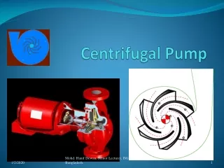
Centrifugal Pump. HOW DOES A CENTRIFUGAL PUMP WORK? Fluid enters the impeller axially through the eye then by centrifugal action or force continues radially and discharges around the entire circumference.

E N D
Centrifugal Pump Mohd. Hanif Dewan, Senior Lecturer, IMA, Bangladesh.
HOW DOES A CENTRIFUGAL PUMP WORK? • Fluid enters the impeller axially through the eye then by centrifugal action or force continues radially and discharges around the entire circumference. • The fluid in passing through the impeller receives energy from the vanes giving an increase of pressure and velocity. • The kinetic (velocity) energy of the discharging fluid is partly converted to pressure energy by suitable design of impeller vanes and volute casing. Mohd. Hanif Dewan, Senior Lecturer, IMA, Bangladesh.
Centrifugal Pump Mohd. Hanif Dewan, Senior Lecturer, IMA, Bangladesh.
Centrifugal Pump Components Mohd. Hanif Dewan, Senior Lecturer, IMA, Bangladesh.
Component division • A centrifugal pump has two main components: • A rotating component • comprised of an impeller and a shaft • A stationary component • comprised of a volute casing, casing cover, and bearings. Mohd. Hanif Dewan, Senior Lecturer, IMA, Bangladesh.
CENTIFUGAL PUMP Mohd. Hanif Dewan, Senior Lecturer, IMA, Bangladesh.
IMPELLER1. Impeller serves to convert mechanical energy of the pump into velocity energy of fluid which is pumped continuously2. The liquid gets the centrifugal force by the rotation of impeller and the liquid from the suction eye continually thrown to the periphery of the impeller. Vanes of ImpellerVane is blades of the impeller as a place of passage of fluid in the impeller. The Eye of ImpellerThe eye of impeller is the entrance side of suction direction of impeller. Mohd. Hanif Dewan, Senior Lecturer, IMA, Bangladesh.
Impellers of pumps are classified based on the number of points that the liquid can enter the impeller and also on the amount of webbing between the impeller blades. Impellers can be either single- suction or double-suction. • A single-suction impeller allows liquid to enter the center of the blades from only one direction. A double-suction impeller allows liquid to enter the center of the impeller blades from both sides simultaneously giving twice the discharge at a given head.. Mohd. Hanif Dewan, Senior Lecturer, IMA, Bangladesh.
Impellers designs can be • Open, • Semi-open, • Enclosed. • The open impeller consists only of blades attached to a hub. • The semi-open impeller is constructed with a circular plate (the web) attached to one side of the blades. • The enclosed impeller has circular plates attached to both sides of the blades are also referred to as shrouded impellers. Mohd. Hanif Dewan, Senior Lecturer, IMA, Bangladesh.
Open Semi-open Shrouded Mohd. Hanif Dewan, Senior Lecturer, IMA, Bangladesh.
DIFFUSER • In some pumps, diffusers are used. These consist of a floating ring of stationary guide vanes surrounding the impeller. • The purpose of the diffuser is to increase the efficiency of the centrifugal pump by allowing a more gradual expansion and less turbulent area for the liquid to reduce in velocity. • The diffuser vanes are designed in a manner that the liquid exiting the impeller will encounter an ever- increasing flow area as it passes through the diffuser. This increase in flow area causes a reduction in flow velocity, converting kinetic energy into flow pressure. Mohd. Hanif Dewan, Senior Lecturer, IMA, Bangladesh.
VOLUTE CASING • The volute casing is like a divergent nozzle which is wrapped around the impeller and serves two main functions • (1) It enables velocity energy to be converted into pressure energy, the degree of conversion is governed mainly by the degree of divergence • (2) It accommodates the gradual increase in quantity of fluid that builds at discharge from the circumference of the impeller. Mohd. Hanif Dewan, Senior Lecturer, IMA, Bangladesh.
For the velocity to be constant the volute is made so that cross sectional pipe area increases uniformly from cutwater to throat. With an impeller having six vanes than the cross sectional area of volute at first vane will be 1/6th of the throat area as one vane is pumping 1/6th of water quantity, similarly 1/3rd at second vane and so on, taking vanes in turn from cut water to throat. • If the discharge line were chocked or blocked then the pump would merely churn water so the fitting of relief valve is not essential. Mohd. Hanif Dewan, Senior Lecturer, IMA, Bangladesh.
Pumps of this type are called double volute pumps (they may also be referred to a split volute pumps). In some applications the double volute minimizes radial forces imparted to the shaft and bearings due to imbalances in the pressure around the impeller. Mohd. Hanif Dewan, Senior Lecturer, IMA, Bangladesh.
Volute casing Mohd. Hanif Dewan, Senior Lecturer, IMA, Bangladesh.
ShaftShaft serves to continue the torque from the drive during operation and the seat of the impeller and other rotating parts.- Shaft is to transmit the torques, - Support the impeller and other rotating parts,- Minimum clearance between the rotating and stationary partsLoads involved are: - Torque, - Weight of the parts, and - Both the radial and axial hydraulic forces. Shaft sleeveShaft sleeve serves to protect the shaft from erosion, corrosion and wear of the stuffing box. In multi-stage pump can be as leakage joint, internal bearings and inter stage or distance sleeve. Mohd. Hanif Dewan, Senior Lecturer, IMA, Bangladesh.
Wearing Rings • Centrifugal pumps contain rotating impellers within stationary pump casings. To allow the impeller to rotate freely within the pump casing, a small clearance is designed to be maintained between the impeller and the pump casing. • To maximize the efficiency of a centrifugal pump, it is necessary to minimize the amount of liquid leaking through this clearance from the high pressure or discharge side of the pump back to the low pressure or suction side Mohd. Hanif Dewan, Senior Lecturer, IMA, Bangladesh.
Some wear or erosion will occur at the point where the impeller and the pump casing nearly come into contact. • This wear is due to the erosion caused by liquid leaking through this tight clearance and other causes. • As wear occurs, the clearances become larger and the rate of leakage increases. Eventually, the leakage could become unacceptably large and maintenance would be required on the pump Mohd. Hanif Dewan, Senior Lecturer, IMA, Bangladesh.
To minimize the cost of pump maintenance, many centrifugal pumps are designed with wearing rings which are replaceable rings that attached to the impeller and/or the pump casing to allow a small running clearance between the impeller and the pump casing without causing wear of the actual impeller or pump casing material. • These wearing rings are designed to be replaced periodically during the life of a pump and prevent the more costly replacement of the impeller or the casing. Mohd. Hanif Dewan, Senior Lecturer, IMA, Bangladesh.
Stuffing Box • In almost all centrifugal pumps, the rotating shaft that drives the impeller penetrates the pressure boundary of the pump casing. It is important that the pump is designed properly to control the amount of liquid that leaks along the shaft at the point that the shaft penetrates the pump casing. • Factors considered when choosing a method include the pressure and temperature of the fluid being pumped, the size of the pump, and the chemical and physical characteristics of the fluid being pumped. Mohd. Hanif Dewan, Senior Lecturer, IMA, Bangladesh.
One of the simplest types of shaft seal is the stuffing box which is cylindrical space in the pump casing surrounding the shaft. • Rings of packing material are placed in this space to form a seal to control the rate of leakage along the shaft. • The packing rings are held in place by a gland which is in turn, held in place by studs with adjusting nuts. • As the adjusting nuts are tightened, they move the gland in and compress the packing. This axial compression causes the packing to expand radially, forming a tight seal between the rotating shaft and the inside wall of the stuffing box. Mohd. Hanif Dewan, Senior Lecturer, IMA, Bangladesh.
The high speed rotation of the shaft generates a significant amount of heat as it rubs against the packing rings. • If no lubrication and cooling are provided to the packing, the temperature of the packing increases to the point where damage occurs to the packing, the pump shaft, and possibly nearby pump bearings. • Stuffing boxes are normally designed to allow a small amount of controlled leakage along the shaft to provide lubrication and cooling to the packing. • The leakage rate can be adjusted by tightening and loosening the packing gland. Mohd. Hanif Dewan, Senior Lecturer, IMA, Bangladesh.
Gland Packing Mohd. Hanif Dewan, Senior Lecturer, IMA, Bangladesh.
Mechanical Seals Mohd. Hanif Dewan, Senior Lecturer, IMA, Bangladesh.
Lantern Ring • It is not always possible to use a standard stuffing box to seal the shaft of a centrifugal pump. The pump suction may be under a vacuum so that outward leakage is impossible or the fluid may be too hot to provide adequate cooling of the packing. These conditions require a modification to the standard stuffing box. • One method of adequately cooling the packing under these conditions is to include a lantern ring Mohd. Hanif Dewan, Senior Lecturer, IMA, Bangladesh.
A lantern ring is a perforated hollow ring located near the center of the packing box that receives relatively cool, clean liquid from either the discharge of the pump or from an external source and distributes the liquid uniformly around the shaft to provide lubrication and cooling. • The fluid entering the lantern ring can cool the shaft and packing, lubricate the packing, or seal the joint between the shaft and packing against leakage of air into the pump in the event the pump suction pressure is less than that of the atmosphere. Mohd. Hanif Dewan, Senior Lecturer, IMA, Bangladesh.
“Balancing Holes” Mohd. Hanif Dewan, Senior Lecturer, IMA, Bangladesh.
BALANCING HOLES IN IMPELLERS • The impeller sometimes contains balancing holes that connect the space around the hub to the suction side of the impeller. • The balancing holes have a total cross-sectional area that is considerably greater than the cross-sectional area of the annular space between the wearing ring and the hub. • The result is suction pressure on both sides of the impeller hub, which maintains a hydraulic balance of axial thrust. Mohd. Hanif Dewan, Senior Lecturer, IMA, Bangladesh.
Centrifugal Pump Classification by Flow • The manner in which fluid flows through the pump is determined by the design of the pump casing and the impeller. • The three types of flow through a centrifugal pump are • Radial flow, • Axial flow, • Mixed flow. Mohd. Hanif Dewan, Senior Lecturer, IMA, Bangladesh.
Radial Flow Pumps • In a radial flow pump, the liquid enters at the center of the impeller and is directed out along the impeller blades in a direction at right angles to the pump shaft. • The impeller of a typical radial flow pump and the flow through a radial flow pump are shown in Figure Mohd. Hanif Dewan, Senior Lecturer, IMA, Bangladesh.
Radial Flow Centrifugal Pump Mohd. Hanif Dewan, Senior Lecturer, IMA, Bangladesh.
Axial Flow Pumps • In an axial flow pump, the impeller pushes the liquid in a direction parallel to the pump shaft. • Axial flow pumps are sometimes called propeller pumps because they operate essentially the same as the propeller of a boat. • The impeller of a typical axial flow pump and the flow through a radial flow pump are shown in Figure Mohd. Hanif Dewan, Senior Lecturer, IMA, Bangladesh.
Axial Flow Centrifugal Pump Mohd. Hanif Dewan, Senior Lecturer, IMA, Bangladesh.
Mixed Flow Pumps • Mixed flow pumps borrow characteristics from both radial flow and axial flow pumps. • As liquid flows through the impeller of a mixed flow pump, the impeller blades push the liquid out away from the pump shaft and to the pump suction at an angle greater than 90o. • The impeller of a typical mixed flow pump and the flow through a mixed flow pump are shown in Figure Mohd. Hanif Dewan, Senior Lecturer, IMA, Bangladesh.
Mixed Flow Centrifugal Pump Mohd. Hanif Dewan, Senior Lecturer, IMA, Bangladesh.
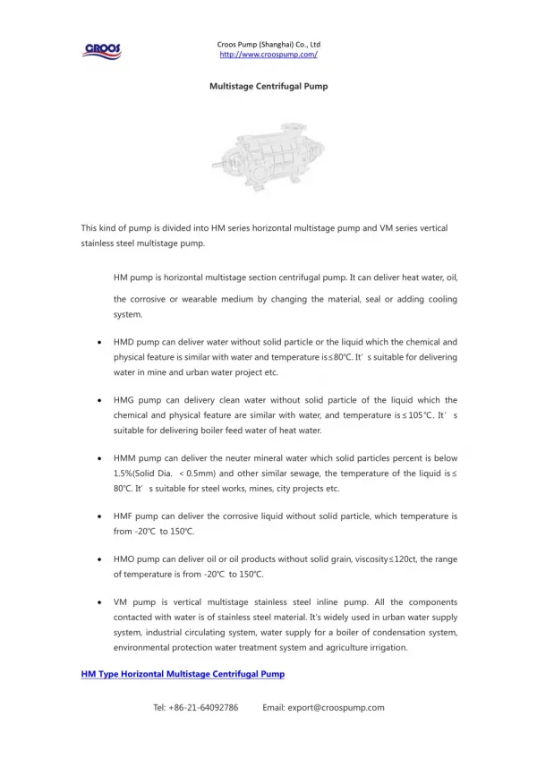
Multi-stages Centrifugal Pump • A pump stage is defined as that portion of a centrifugal pump consisting of one impeller and its associated components. • Most centrifugal pumps are single-stage pumps, containing only one impeller. • A pump containing seven impellers within a single casing would be referred to as a seven-stage pump or generally considered as a multi-stage pump. Mohd. Hanif Dewan, Senior Lecturer, IMA, Bangladesh.
A centrifugal pump with a single impeller that can develop a differential pressure of more than 150 psid between the suction and the discharge is difficult and costly to design and construct. • A more economical approach to developing high pressures with a single centrifugal pump is to include multiple impellers on a common shaft within the same pump casing at moderate speed. • Internal channels in the pump casing route the discharge of one impeller to the suction of another impeller Mohd. Hanif Dewan, Senior Lecturer, IMA, Bangladesh.
The water enters the pump from the top left and passes through each of the four impellers in series, going from left to right. • The water goes from the volute surrounding the discharge of one impeller to the suction of the next impeller. Mohd. Hanif Dewan, Senior Lecturer, IMA, Bangladesh.
Multi-Stage Centrifugal Pump Mohd. Hanif Dewan, Senior Lecturer, IMA, Bangladesh.
PRIMING OF CENTRIFUGAL PUMPSCentrifugal force does not act on the air. So, if there is air in the system, it will make problem for the operation of a centrifugal pump. The procedure to remove the air from a system is called the priming.All centrifugal pumps are NOT self priming pumps, and therefore for them to function properly they have to be primed.A centrifugal pump is said to be primed when the waterways of the pump are full with the liquid. When first put into service, the waterways are filled with air. If the suction supply is above atmospheric pressure that is the suction head is positive, then this air will be trapped in the pump and form an air lock. The only way to get rid of it by opening a vent valve and releasing it. If on the other hand the suction is negative or below atmospheric then priming can be accomplished by using a foot valve in the suction line and using some form of vacuum-producing device.
WET VACUUM PUMPS (ROTARY AIR PUMP OR WATER RING TYPE AIR PUMP)This pump consists of a circular bladed rotor with forward swept vanes, fitted on the pump spindle and rotating in an elliptical casing. Outside this casing is a reservoir containing fresh water with gravity feed. Mohd. Hanif Dewan, Senior Lecturer, IMA, Bangladesh.
When the rotor rotates concentric to the axis the water in the casing is driven to the outside of the ellipse. This water therefore recedes from and approaches the centre twice per revolution, producing in effect a series of reciprocating water pistons between the vanes. There are two suction and two discharge ports set in a plate which is adjustable for running clearances. The suction ports are connected to a point near the impeller suction eye by means of a pipe. When the centrifugal pump is started this rotary air pump also starts as it is mounted on the same shaft. Mohd. Hanif Dewan, Senior Lecturer, IMA, Bangladesh.