Download
1 / 26
270 likes | 548 Views
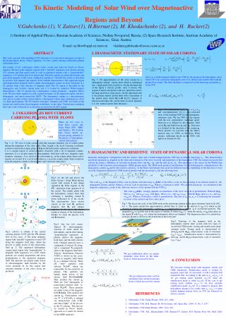
Western Electricity Coordinating Council Modeling and Validation Work Group Renewable Energy Modeling Task Force REMTF Solar and Wind Modeling Update Contact: Abraham Ellis aellis@sandia.gov Tempe, AZ November 18, 2010.

E N D
Western Electricity Coordinating CouncilModeling and Validation Work GroupRenewable Energy Modeling Task ForceREMTF Solar and Wind Modeling UpdateContact: Abraham Ellisaellis@sandia.govTempe, AZNovember 18, 2010 Sandia is a multiprogram laboratory operated by Sandia Corporation, a Lockheed Martin Company, for the United States Department of Energy’s National Nuclear Security Administration under contract DE-AC04-94AL85000.
Wind/Solar Modeling Discussion • REMTF Update – Abraham Ellis • Wind Power Plant Modeling • Update on wind generator default data – Ian Hiskens • Update on CEC project on wind power plant model validation – Ed Muljadi • PV generation modeling • PV inverter testing – Richard Bravo • EPCL for adding distributed PV models – Dmitry Kosterev • Approval Items • WECC wind generation dynamic modeling guideline • WECC solar generation power flow modeling guideline
WECC REMTF Charter • The Renewable Energy Modeling Task Force shall • Develop and validate generic, non-proprietary, positive-sequence power flow and dynamic simulation models for solar and wind generation for use in bulk system studies • Implement models in commercial simulation software • Issue guidelines, model documentation • Coordinate with stakeholders
Modeling and Reliability • Lack of industry-standard validated models identified as major issue for variable generation going forward “Validated, generic, non-confidential, and standard power flow and stability (positive-sequence) models for variable generation technologies are needed. Such models should be readily and publicly available to power utilities and all other industry stakeholders. Model parameters should be provided by variable generation manufacturers and a common model validation standard across all technologies should be adopted. The NERC Planning Committee should undertake a review of the appropriate Modeling, Data and Analysis (MOD) Standards to ensure high levels of variable generation can be simulated.” Source: NERC Special Report, Accommodating High Levels of Variable Generation, http://www.nerc.com/files/IVGTF_Report_041609.pdf
WECC REMTF Meetings • Most recent meeting • November 16, Tempe, AZ • PV in the morning, Wind in the afternoon • Attendance 25 people • Significant progress made in both meetings • Planned meetings • February 28 – March 1 2011 in SLC
Wind Summary • Existing Models • Proprietary models still being used, but status quo remains unacceptable and impractical • WT1, WT2, WT3, WT4 generic models implemented in PSSE, PSLF and other software, approved by MVWG • Factors slowing adoption of generic models • Model structure does not fit some manufacturers (especially WT3) • Few parameter sets model validation • Some disagreement on technical requirements for planning models • Unclear expectations from compliance organizations • Old versions of simulation programs
Wind Summary • REMTF addressing known issues in Phase 2 • Revisions to the models • WT1 needs modifications to aerodynamic control • WT3 needs significant modifications (most important!) • WT4 are in good shape • Model validation/verification, parameter sets • Key collaborating efforts • EnerNex project: validation against manufacturer models • EPRI project: validation against field data • Fruitful technical exchange through IEC TC88/WG27 • IEEE working group
Proposed Modifications to WT3 • Current control during fault • Fundamental difference between GE WTG and other WTGs • May need to define two generic WT3 models • Agreed to adopt proposal • Crowbar or dynamic breaking • How to capture DC capacitor control/protection during faults • Would require more significant changes to the model structure • Significance of this issue to be studies by next meeting • Unbalanced fault tolerance • WTG may trip due to excessive negative-sequence current during close-in faults • Agreed to address as a guideline, need manufacturer input
Proposed Extension to WT3 Three changes proposed to better represent WT3 behavior during a short curtuit. Reference- PSLF Manual.
Proposed Extension to WT3 Move generator pseudo magnetizing reactance from bus bar to inside controller. Add current limitation and active/reactive current priority blocks Add two pseudo current-loop controller blocks Pgen From wt3e Physical motivation for current loops: 1) Inverters typically have two current loops associated with d-q current loops. 2) Based on dynamic averaging techniques, the inverters are approximated by a simple lag time controller. 3) In d-q space, PI controllers are common because zero error tracking is possible. To wt3t
Proposed EPM Extension to WT3 Reference- Erlich’s Group Presentation
Verification Against a WT3 (Gamesa) Reactive current appears to capture the essence of the current. Note that the real current is going down during the fault. The oscillation in the real power is due to the shaft compliance oscillation and currently is not being captured in the extended model (of EnerNex)
Numerical Stability Issues Integrators cause too much phase lag (i.e., each create 90◦ lag). Replace Q-loop controller with structure similar to what’s in the P-loop controller .
Solar Summary • Existing Models for Large-Scale PV Systems • Current versions of PSLF and PSSE have PV model • Based on WT4 model implementation • REMTF has proposes several modifications • Treatment of DC dynamics (REMTF determined that there is no need to represent DC dynamics at all) • Up-ramp rate limiting • Simulation of variability • WECC distribution-connected PV models • Residential model (fixed power factor) • Distribution-connected utility-scale model (possibly providing dynamic reactive power support)
Central-Station PV System Model Network Model (implemented in PSLF or PSS/E) DC Voltage D- and Q-Axis Voltage PV Array Model Inverter Model Solar Irradiance DC Current D- and Q-Axis Current Reactive Power Control Model Initial PF Desired Q-Axis Current Grid Protection Model AC Bus Voltage
Existing PSLF PV Model (also in PSSE) ewtgfc gewtge Source: K. Clark, N. Miller, R. Walling, “Modeling of GE Solar Photovoltaic Plants for Grid Studies”, April 2010 • Existing, usable model; default data for GE product • Model based on existing GE Type 4 WTG model • Converter dynamics dominates model dynamics • DC-side dynamics (MPPT, dc capacitor dynamics) assumed very fast, ignored in the model
Proposed Residential PV Model • In load flow, net PV with load • Q = 0, P into constant power term • New proposal: allow Q ≠ 0 • For dynamics, PV represented as a part of the WECC CMPLDW model (similar to electronic load)
Proposed Distributed PV Model Structure in Power Flow in CMPLDW model Fma * PL 1. – Fdg M M Fmb * PL 1. – Fdg PL 115-kV 230-kV M Fmc * PL 1. – Fdg Fmd * PL 1. – Fdg M Fel * PL 1. – Fdg Electronic UVLS Static UFLS Res. PV gen. (1. - Fma - Fmb - Fmc - Fmd – Fel) * PL * 1. / (1 – Fdg) Fdg * PL 1. - Fdg
Dynamic Model For Residential PV To be modified to allow for Q ≠ 0 (fixed)
Proposed Commercial PV Model • In load flow, model PV behind feeder impedance • Preserve identity of equivalent inverter terminals • For dynamics, use stand-alone dynamic model with basic reactive power control
Irradiance to Power • Over very short timeframes seconds, power variability is less than irradiance variability • Power is smoothed out by array footprint and geographical dispersion of distributed systems • Proposal: • Porder = Po x Variability Factor (range is 0 to 1) • Variability factor to be defined off-line • Address in guidelines and model documentation • Provide library of data samples
Wind Modeling Guides • Load Flow Modeling Guide (completed in 2009) • Dynamic Modeling Guide (Submitted for review 8/2010)
Solar Modeling Guides • Load Flow Modeling Guide (submitted for review in 08/2010) • Dynamic Modeling Guide (model development underway)