Download
1 / 35
350 likes | 471 Views
This presentation outlines the latest developments in tropical cyclone research, specifically focusing on the Advanced Objective Dvorak Technique (AODT) and Tropical Cyclone Intensity Estimate (TIE) Model. Key improvements include enhanced scene type classifications, refined intensity estimates, and a new latitude bias adjustment strategy that significantly reduces errors in storm intensity estimates. These advancements improve the operational capabilities for forecasting and intensity assessment, facilitating better understanding and prediction of tropical cyclone behaviors.

E N D
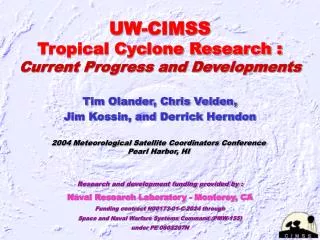
UW-CIMSSTropical Cyclone Research :Current Progress and Developments Tim Olander, Chris Velden, Jim Kossin, and Derrick Herndon 2004 Meteorological Satellite Coordinators Conference Pearl Harbor, HI Research and development funding provided by : Naval Research Laboratory - Monterey, CA Funding contract N00173-01-C-2024 through Space and Naval Warfare Systems Command (PMW-155) under PE 0603207N
UW-CIMSS Tropical Cyclone Research Briefing Overview • Advanced Objective Dvorak Technique (AODT) • Tropical cyclone Intensity Estimate (TIE) Model • AMSU • Environmental Shear Estimates
AODT – Latest Improvements • Added new scene type classifications • Separate classifications for eye and surrounding cloud regions • Eye: Clear, Pinhole, Large, Ragged, Obscured, None • Cloud: Uniform, Embedded Center, Irregular CDO, Curved Band, Shear • Scenes more closely mimic Dvorak Technique classifications • Convective symmetry parameter used to classify cloud region • Expanded for tropical storm and weaker systems • Utilize Curved Band analysis as defined in Dvorak EIR Technique • to estimate cloud curvature signatures • Irregular CDO scene covers “transition” scenes • Removed Rapid Flag / modified time averaging scheme • Final T# changed from 12-hour to 6-hour weighted average • New technique still allows for rapid intensification
AODT – Latest Improvements • Modified land interaction rule • Analysis suspended while storm is over land (keyword override) • Rule 9 application stopped after storm is over land for >12 hours • Added Dvorak EIR Technique Rule 8 • Constrains growth/decay rate of storm intensity over time • Position of maximum Curved Band analysis determined • Location provided in addition to manual position values
AODT – Latest Improvements (continued) • Latitude bias adjustment applied to CI# value • A bias was found in Dvorak EIR Technique related to latitude • The bias is caused by the latitudinal variation of eyewall • cloud-top temperature, resulting from the latitudinal • variation of tropopause temperature • Bias adjustment increases/decreases intensity for storm • positions north/south of approximately 22ºN latitude • Adjustment based on linear regression and applied to CI# value • Adjusted and unadjusted CI# values stored in AODT history file • Reduces MSLP estimate error by about 10% in test cases • This bias should also be applied to conventional Dvorak method
Latitude-dependent bias in Dvorak Enhanced IR (EIR)technique applied to Atlantic TC’s. The bias explains 15% to 20% of the variance of error. The overall bias is always between ±1.5mb and appears benign, but the latitude-dependent bias is as large as –10mb at 10°N and +14mb at 40°N.
Application to other oceanic basins: Mean tropopause temperature (NCEP reanalysis). Averaged over AUG SEP OCT (FEB MAR APR) in Northern (Southern) hemisphere. WMO-RMSC regions
AODT-v6.3 – Results Including Latitude Bias Adjustment Homogeneous Comparisons with Aircraft Reconnaissance (26 storms between 1995 and 2002) All Tropical Cyclone Intensities (MSLP) (errors in millibars) Bias RMSE Sample AODT adj 0.09 9.50 1630 AODT unadj 0.42 10.72 1630 Op Centers 0.22 10.65 1630 Note: Positive error indicates underestimate (e.g. AODT minus Recon)
AODT – Latest Improvements (continued) • Improved automated center location determination scheme • Operational Center forecast used as first guess • JTWC or NHC forecasts used in conjunction with • 6 and 12 hour old positions from AODT history file • Current position interpolated using polynomial interpolation scheme • Laplacian Analysis of cloud top region performed • Analysis region within 75 km radius of interpolated forecast position • Identifies pixels with strong gradients in cloud top temperature field • Confidence factors derived for each methodology • Forecast : Time difference from “Initial/Warning” position • Laplacian : Density and scatter of large temperature gradients • Laplacian typically only used where strong but concentrated • temperature gradient fields are identified (e.g. Eye Scenes)
AODT Auto-Positioning Comparison Hurricane Floyd AODT Auto-Position Clear Eye 6.2 T# NHC Interpolated Forecast Position Uniform Cloud Region 4.5 T#
AODT-v6.3 – Results Automated AODT Homogeneous Comparisons with Aircraft Reconnaissance Dependent Data Sample (26 storms between 1995-2002) (errors in millibars) Bias RMSE Sample AODT Manual 0.09 9.50 1630 AODT Automated 1.70 10.04 1630 Op Centers 0.22 10.65 1630 Independent Data Sample (5 storms in 2003) (errors in millibars) Bias RMSE Sample AODT Automated 2.40 9.93 522 Op Centers 2.67 11.81 522 Note: Positive error indicates underestimate (e.g. AODT minus Recon)
AODT-v6.3 – Results Homogeneous Comparisons with Aircraft Reconnaissance Statistical Breakdown by AODT scene type (errors in T# units) Bias RMSE AAE Sample All Points 0.11 0.67 0.51 3735 All Eye Scenes -0.08 0.50 0.40 1063 Clear Eye -0.02 0.42 0.32 445 All other Eye -0.12 0.55 0.46 618 All Non-Eye Scenes 0.19 0.73 0.56 2672 Uniform CDO 0.17 0.64 0.51 1093 Embedded Center 0.19 0.66 0.46 193 Irregular CDO 0.11 0.70 0.55 278 Curved Band 0.17 0.73 0.60 324 Shear 0.25 0.85 0.64 784 Note: Positive error indicates overestimate (e.g. AODT minus Recon)
AODT – Future Directions • Integrate regression-based TIE Model with AODT • Use 2003 TC results to guide development of combined method • Examine additional geostationary channels • IRW-WV channel difference (Velden and Olander, 1998) • Additional Dvorak methods using visible and/or shortwave infrared • Investigate additional satellite information • AMSU analysis using technique developed at UW-CIMSS • SSM/I and TRMM analysis based on work by NRL-MRY/R. Edson • GOAL • Develop an advanced multi-sensor objective technique • Fuse results/output from different instruments and analysis techniques into an expert system
IRW-WV channel difference Microwave imagery Current AODT Integrated Satellite-Based TC Intensity Estimation System AMSU
AODT – Availability • The latest version of the AODT is currently available to any/all interested users for McIDAS platforms from the AODT webpage (along with the updated Users’ Guide) • The latest version of the AODT is being integrated into the TeraScan system for use at JTWC during the 2004 TC season. The code has also been adapted for N-AWIPS at NOAA sites and Mark-IVB at AFWA • An X-Window/Motif version of the AODT has also been developed and will is available for UNIX and Linux based systems (also available at the AODT webpage) AODT webpage http://cimss.ssec.wisc.edu/tropic/aodt
The Tropical cyclone Intensity Estimation (TIE) model: • Developed to formally explore the relationships between TC intensity and features in geostationary satellite infrared (IR) imagery, without the constraints of the Dvorak-based methods and their attendant rules. • Applicable at all stages of TC lifetime. • Completely objective; no scene-typing.
} Predictor (sig > 99.9%) Normalized Coefficient Warmest eye temperature – 0.64 Mean eyewall temperature + 0.43 Symmetric organization + 0.34 SST-based parameter + 0.26 Latitude – 0.16 IR-derived TIE-model: multivariate linear regression TC central pressure (MSLP) measured from aircraft reconnaissance is regressed onto 5 predictors 63% of the MSLP variance is explained by the regression.
TIE-model performance: Errors relative to recon. TIE-model errors based on independent jackknife analysis.
The good: The bad: TIE-model performance:
TIE-model R&D: • Serves as a natural platform for testing additional parameters for correlation with TC intensity. • Indices derived from synoptic fields (analogous to SHIPS) are being presently tested. • Further development will include indices derived from microwave imagery; these can include indices related to eyewall replacement cycles. • TIE model estimates will be available in conjunction with AODT estimates on TeraScan system this coming season.
AMSU-A passive microwave radiometer • Flown on NOAA-15/16/17 and Aqua polar orbiting satellites • Up to 6 warm core observations daily (NOAA birds) • Senses terrestrial radiation near 55GHz region • Challenges • Scattering prohibits hydrostatic integration • Variability in peak warming altitude • Variable horizontal resolution FOV 1 FOV 30 AMSU Background • What does AMSU really observe?
Hurricane Inez 1966 8 929hPa 7 6 Hurricane Floyd 1999 5 Suitability of the AMSU
10 ? 0 1013 930 AMSU MSLP CIMSS AMSU-based TC Intensity Estimation Algorithm • Extrapolate storm position for AMSU pass time • based on latest warning • Find max AMSU Tb in ch7 and 8 within 100km • of storm position (this is the TC upper-level warm core) • Average environmental Tbs from 4 surrounding points and • subtract from core value to determine thermal anomaly • Estimate MSLP for ch7 and ch8 anomalies based on • statistical regression. Use lower of the two values. • Apply FOV bias correction based on RMW or... • Call channel 7 retrieval if: • Raw Ch7 Tb anomaly > Raw Ch8 • Raw Ch7 anomaly > 1.0K • Storm is located near the edge of the satellite swath X X
2002 Results (MSLP) Statistics for Atlantic (N= 60) in hPa CIMSS Dvorak Mean Error 3.29 4.52 Std Dev 2.30 3.40 Bias -0.08 -0.90 RMSE 4.00 5.62 Avg MSLP of sample 1002.4 Statistics for Pacific (N = 10) in hPa CIMSS JTWC Mean Error 8.00 11.16 Std Dev 7.25 8.79 Bias 4.79 6.10 RMSE 10.57 13.93 Avg MSLP of sample 964.4
2002 Atlantic Basin Results NOAA/NESDIS Satellite Analysis Branch (SAB) vs. AMSU (N=34, +/- 2hrs of aircraft reconnaissance) SAB 78% within +/- 0.5T AMSU 81% within +/- 0.5T
Sources of Error • Radius of Maximum Winds • Used as a proxy for eye size in algorithm • Especially important for small intense storms • How is it determined? • Position • First Guess comes from Warning Message • Search algorithm locates max anomaly • Sheared systems
Improve Technique • Bias correction when storm is near satellite limb • Separate treatment of pinhole eye storms using new coefficients • Time averaging / smoothing • Add channel 8 retrieval • Remove precipitation contamination (Bob Wacker) • Addition of AMSU on Aqua (2 more passes per day) • Basin specific coefficients (need sufficient “observations”) Confidence Indicator ? • Give forecasters a measure of estimate confidence • Based on FOV, eye size (RMW), anomaly height Future Work
AMSU-generated MSLP estimate accuracy improved in 2002 • Addition of second AMSU channel and advanced logic • Skill comparable to, and in some cases better than, the Dvorak estimates • Future changes will improve performance Summary and Conclusions AMSU provides unique tropical cyclone perspective • Can see beneath upper level cloud cover • 55 Ghz region radiances can quantify inner core thermal • structure / changes. • Temperature anomaly strength directly associated with tropical • cyclone intensity • A unique addition to the forecaster “tool kit”
UW-CIMSS/NESDIS wind shear products in Hurricane Lili (2002) Deep-layer Tendency Mid-level
CIMSS experimental vertical shear product (Gallina and Velden 2002) TROPICAL STORM KYLE 18:00UTC 07October2002 UW-CIMSS Experimental Vertical Shear TC Intensity Trend Estimates Current Conditions : Latitude : 32:19:27 N Longitude : 70:50:45 W Intensity (MSLP) : 1005.0 hPa Max Pot Int (MPI) : 971.7 hPa MPI differential (MSLP-MPI) : 33.3 hPa CIMSS Vertical Shear Magnitude : 2.8 m/s Direction : 215.0 deg Outlook for TC Intensification Based on Current Env. Shear Values Forecast Interval : 6hr 12hr 18hr 24hr F F N N Legend: VF - Very Favorable F - Favorable N - Neutral U – Unfavorable VU - Very Unfavorable -- Mean Intensity Trend (negative indicates TC deepening) -- 6hr 12hr 18hr 24hr VF < -3.0mb/ 6hr < -6.0mb/12hr < -9.0mb/18hr < -12.0mb/24hr F -3.0 - -1.5 -6.0 - -3.0 -9.0 - -4.5 -12.0 - -6.0 N -1.5 - +1.5 -3.0 - +3.0 -4.5 - +4.5 -6.0 - +6.0 U +1.5 - +3.0 +3.0 - +6.0 +4.5 - +9.0 +6.0 - +12.0 VU >+3.0 >+6.0 >+9.0 >+12
SUMMARY During the 2002 TC season, a fully automated algorithm based partially on quantitative satellite data estimates of environmental wind shear was used to derive short-term TC intensity outlooks in real time. The experimental output products were distributed by CIMSS via email to selected Tropical Analysis Centers. Preliminary analysis and forecaster feedback suggests these products can be quite useful as indicators of favorable/unfavorable tropospheric environments precluding TC deepening/filling trends. Quantitative relationships between shear and short-term TC intensity trends were developed based on an exhaustive statistical analysis of shear fields produced at CIMSS using satellite-derived wind information. The resulting prognostic algorithm shows preliminary evidence of skill over SHIPS and other methods in some cases.
RESULTS 1) Qualitatively, the new shear products are showing promise to aid the TC intensity forecast process. Initial assessment and feedback from Tropical Analysis Centers has been quite favorable. 2) In general, intensity trends are related to changes in the environmental shear as depicted by the CIMSS fields and outlook products. The short term (24-hr) intensity trend outlook (deepening or filling) was correct 93% of the time. 3) Case studies illustrate situations when shear thresholds and trends in shear can be indicators of TC intensity changes. 4) The more quantitative, experimental outlook product based on a statistical analysis of the CIMSS shear estimates vs. observed TC intensity was skillful relative to SHIPS and other guidance in Lili, but not in Kyle. Further analysis is underway.