Download
1 / 24
240 likes | 267 Views
Learn about innovative methods combining plasma technology and sorbent filtration for CBRN protection in confined spaces. Plasma reactor design, modular systems, and breathable air stages are explored for efficient decontamination.

E N D
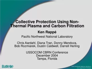
Collective Protection Using Non-Thermal Plasma and Carbon Filtration Ken Rappé Pacific Northwest National Laboratory Chris Aardahl, Diana Tran, Donny Mendoza, Bob Rozmiarek, Dustin Caldwell, Darrell Herling USSOCOM CBRN Conference December 2004 Tampa, Florida
Outline • Concept Introduction/Motivation • Non-Thermal Plasma (NTP) • NTP-Carbon Hybrid • Modular System for CBRN Protection • NTP reactor design – power delivery • Breathable air stages – design and selection • Assess NOx & ozone production from NTP • Activated carbon polishing • Live Agent Work
System Requirements • Confined Space Application • Requirements: • Portable • Specified flow of at least 10 CFM • Limited power availability • Simplistic in start-up and operation • Minimal maintenance and logistics • Simplistic operation-to-operation maintenance
Non-Thermal Plasma:Dielectric Barrier Discharge • Only electrons are ‘hot’. • Gas can be passed through discharge resulting in treatment. • Gas remains relatively cool, hence the common term of ‘cold plasma’. Similar to a neon sign. • Active species for oxidation include N2+, O2+, N•, O•, •OH, •O2H, and O3.
3 2.5 1000 ppm 2 /C) 0 500 ppm 1.5 Ln(C 1 100 ppm 0.5 0 0 500 1000 1500 2000 Energy Deposited (Ê), J/L NTP Typical Data Set Chlorobenzene in Air Inert packing – glass Ln(C0/C) = Ê/b Ê=P/Q J/L More energy required as concentration
Motivation for Hybrid System • 500 ppm Acetonitrile in Air with Pt/Pd catalyst in NTP at room temp. • Drawback of NTP is that very high degree of organic destruction is prohibitive due to high energy cost. • Energy cost for 80-90% contaminant destruction is manageable. • Solution is to integrate plasma with sorbent. 99.99% 99.9% 99%
Carbon Breakthrough Simple Breakthrough Model: Wheeler C0 decrease = tb increase C* - NIOSH safe contaminant level T* - Carbon life (breakthrough time) Contaminant destruction via NTP extends carbon life (T*), providing extended active protection and minimizing size.
CBRN Protection Employing NTP • Aggressive and non-selective oxidation: C & B • Charge delivered to particulates for effective collection: B & R/N • Operation at low temperature • Advantage over other oxidation technologies • Minimal maintenance and reduced logistics • Advantage over sorption alone
Breathable Air • Long time challenge for NTP is the production of noxious gases during gas treatment. • Assess products of NTP processing Acid gases: HCl, H3PO4, SOx, HF, etc. NOx: NO, NO2 Ozone: O3 • Evaluate ozone degradation catalyst and acid gas getter materials • Size breathable air filtration stages • Determine suitable polishing medium Trade-off of plasma and catalyst stage size
Non-Thermal Plasma ReactorProducts for Varying Humidity Design 1.25 kW
Modular System for CB Protection Non-Thermal Plasma Agent + Air Breathable Air Acid Gas Sorbent Polsihing Media Ozone Catalyst Plasma results in aggressive non-selective oxidation. PM trapped and destroyed. Organics are oxidized. Plasma targets >90% destruction of chemical species. Polishing stage used to obtain breathable limits.
Plasma Reactor Design:Extremely Compact Forms Possible Sized for a 2.0 liter engine • Development of plasma technology initially focused on diesel exhaust treatment and VOC oxidation alternative to TCO. • Automotive platforms altered for CBRN protection applications. • Reactor Can • Weight: 2.9kg • Length: 82mm • Width: 160mm • Height: 90mm • Reactor Brick • Length: 40mm • Width: 115mm • Height: 46mm • Active Area: 15.4cc
Power Delivery Options • Power delivery is flexible. • 110 or 220 transformers are readily available so worldwide operation from wall power relatively easy. • 12, 18, 24 V also possible through existing power supplies at power levels lower than 1500 W. • Inverters could be used for higher power requirements.
Acid Gas Sorbent • Unisorb Mark 2 • Adsorbent sizing basis • Kinetically Limited • 10,000 ppm slug to 100 ppm • Capacity Limited • 100 ppm constant over 8 hours at 250 L/min air flow rate
Ozone Removal Catalyst • Carulite 200 Catalyst • Production of O3 from Plasma • 300 Watts • 50% rh • 525 ppm O3 • Linear Velocity • Zero order kinetics → 2.2 ft/sec max to obtain desired contact time
3MTM FR-64 Carbon Originally designed for full facepiece military-style respirators for Emergency Response. Has been tested (to military specs) to filter wide range of chemical warfare agents: nerve agents, tear agents, blood agents, chlorine, phosgene, chloropicrin, diphenylchloroarsine. Manufactured in accordance with U.S. MIL-C51560(EA) and EA-C-1704.
Concentration Effect onCarbon Bed Size 8 hour exposure time, 250 L/min air flow 75% Plasma efficiency
Combined Plasma Efficiency and Concentration Effect onCarbon Bed Size 8 hour exposure time, 250 L/min air flow Simulation agent: DMMP
Live Agent Exposure Predictions • For non-persistent agents (chlorine, phosgene, sarin), proximity of source is the critical factor • Near point of release results in high levels • At distances approaching 1 mile there is little to no exposure even if wind is in an unfavorable direction • For persistent agents (VX, mustards), exposure time is critical.
Agent Impact Factors 1 Contact exposure 2 Inhalation exposure
Live Agent WorkCompleted at Dugway Proving Ground • System tested with HD and GB. Performance within specifications. Ozone and Carbon Stages Disseminator, Plasma, and Acid Gas
Future Work • Should be possible to integrate breathable air stages. This will allow even smaller profile. • First prototype focused on chemical hazards. Still needs to be tested against BRN. Likely design changes based on results (eg., pulsed power needed for PM collection). • Need to understand thermal and E-M signature better and potentially shield device. • Begin looking at other applications such as protection of tented structures, buildings, safe havens, and other vehicles.
Conclusion • Plasma-carbon hybrid CP designed and demonstrated. Advantage is smaller/lighter system or longer operational life. • Should be possible to reduce size through integration of stages. • Benefit of approach goes up with air flow requirement. Plasma reactor and power supply size/weight become much less than carbon volume avoided as flow increases. • Likely not suitable for individual protection. • Vehicles, aircraft, tents, and buildings are potentially suitable uses of the technology.