Download
1 / 35
350 likes | 507 Views
Fault-Adaptive Control Technology F33615-99-C-3611. http://www.isis.vanderbilt.edu/Projects/Fact/Fact.htm. ISIS, Vanderbilt University Technical University of Budapest, Hungary Xerox PARC. Gabor Karsai Gautam Biswas Sherif Abdelwahed, Tivadar Szemethy

E N D
Fault-Adaptive Control TechnologyF33615-99-C-3611 http://www.isis.vanderbilt.edu/Projects/Fact/Fact.htm ISIS, Vanderbilt University Technical University of Budapest, Hungary Xerox PARC Gabor Karsai Gautam Biswas Sherif Abdelwahed, Tivadar Szemethy Sriram Narasimhan, Tal Pasternak, John Ramirez Gabor Peceli Gyula Simon, Tamas Kovacshazy Feng Zhao Xenofon Koutsoukos, Jim Kurien
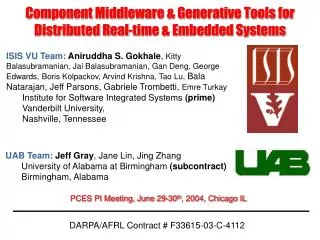
TU Budapest Reconfiguration Transient Management Xerox PARC Alternative Hybrid Diagnostics Boeing OCP Controller modeling OCP realization Berkeley Modeling, FDIR Georgia Tech Reconfiguration technology Northrop/Grumman FDIR Subcontractors & Collaborators
Problem Description, Objective • Problem: To maintain control under fault conditions • Goal: Technology and tool suite for Fault-Adaptive Control • Components: • Modeling approach for capturing • Hybrid and discrete models of the plant for both nominal and faulty behavior • Reconfigurable controllers • Mode identification and real-time fault-diagnostics • Model-based hybrid and discrete approaches • Model-based dynamic selection/synthesis of regulatory controller structures • Algorithms for mitigating reconfiguration transients • SEC contribution: • Integrated Fault detection, isolation, and reconfigurable control
Monitor/ Hybrid Controller Diagnostics Library Active Model Failure Propagation Controller Diagnostics Selector Embedded Models Fault Detector Transient Manager Hybrid Observer Reconfigurable Monitoring and Control Reconfiguration System Controller Technical Approach SummaryFrom models to a run-time system • Visual modeling environment for creating: • Hybrid bond-graph models • Timed failure propagation graph models • Controller models (supervisory and regulatory) • Run-time execution environment for hosting: • Monitoring and controller software • Hybrid and discrete diagnostics modules • Controller object library and selector • Transient manager component • Use OCP as the underlying “OS” Open Control Platform
Hybrid ModelingNew developments • Fault detector specifications • Variables –FD-> Alarms • Modulated components [nonlinearity] • Variable –MOD-> (R,C,I,Sf,Se,TF,GY) • Controller modeling language • SVC + Regulators
Hybrid ObserverNew developments HYBRID OBSERVER MODELS FINITE AUTOMATON • Tracking autonomous changes • Modulated components • Observer is composed automatically from component models N switches 2N modes CONTROL EVENTS AUTONOMOUS EVENTS RECALCULATE KALMAN FILTER EST: xk ,yk uk CONTROLLER yk PLANT MODE CHANGES
Tracked Trajectory Actual Trajectory Mode 5 Mode 4 Fault Occurs Fault Detected Mode 7 Mode 1 Mode 2 Mode 3 Mode 6 Time Line T2 T3 T4 T1 T6 T5 Hybrid Diagnosis New Development: Solution of Hybrid Diagnosis problem for piecewise linear hybrid dynamical systems Presence of fault invalidates tracked mode trajectory If controller model is “correct”, fault must have occurred in one of the modes in the mode trajectory Fault Hypothesis: <mode,parameter> Roll Back to find fault hypotheses Catch up to current system mode to verify hypotheses against measurements Note: Controller transitions known Autonomous transitions have to be hypothesized Known Controlled Transition Hypothesized Autonomous Transition Hypothesized fault mode Possible current modes Hypothesized intermediate modes Roll Forward to confirm fault hypotheses
Hybrid Diagnosis Methodology Issues Addressed: • Tracking, prediction, and analysis of system behavior under fault conditions across discrete mode changes • Deal with parametric faults (multiplicative) that occur as abrupt changes in parameter values • Fault Detection complicated – distinguish between mode change transients and fault transients • Sometimes fault detection occurs after mode change occurs • Requires fast roll back process to identify correct model for fault isolation Issue: What to propagate across mode-change boundaries? • To compare against current behavior, fault signatures have to be generated by a quick roll forward process Issue: Autonomous changes cannot be correctly predicted. Tracking process invokes multiple paths • Parameter estimation • Fault isolation refinement • Fault magnitude determination
Roll Back Process Candidate Set <fault,mode> Hypothesis Generation (Back Propagation) Signal to Symbol Generator Mode mi Past Mode Trajectory Qualitative Hypotheses Refinement Forward Prop + Prog Monitoring Quick Roll Forward Refined Candidate Set <fault,mode> current mode Temporal Causal Graphs (TCGs) Observations Quick Roll Forward Quantitative Hypotheses Refinement Parameter Estimation Transfer function Models Real-time estimation Fault Isolation & Identification From Hybrid Bond Graphs Refined Candidate Set <fault,mode> current mode
- Valve C – Tank Capacity Sf1 R – Pipe Resistance Sf2 Sf – Flow Source Tank1 R1 R5 C1 Tank3 Tank2 C3 C2 R3 R4 R2 R6 Hybrid System ExampleThree Tank System hi = level of fluid in Tank i Hi = height of connecting pipe Hybrid bond graphs relate parameters to system dynamics
Transition Fault Occurred Fault Detected System Autonomous Transition • Tank 1 Pressure • Tank 2 Pressure • Tank 3 Pressure Roll Back Process Fault: Leak in Drain Pipe • Qualitative Hypotheses Generation • Back propagate through TCG in current mode to identify candidates • Back propagate across mode transitions using transition conditions (need to account for reset conditions, and change in plant configuration – invert qualitatively) • Repeat same process for previous modes to identify more candidates Example 1: Leak in pipe Current Mode Candidates = C2+(0-+ ,-+- ,000 ), C1+(-+- ,0-+ ,000 ), R1- (0-+ ,00- ,000 ), R12- (0-+ ,0+- ,000 ) Previous Mode Candidates = C1+(-+- ,000 ,000 ), R1- (0-+ ,000 ,000 )
Quick Roll Forward • Goal: Get to current mode, so parameter estimation can be applied to refine faults and identify fault magnitude • Lemma: Sequence of k mode transitions in any order drives the system to the same final model • Requires tracking of transients by progressive monitoring in continuous regions of space. Taylor series expansion defines qualitative fault signatures. Residual r(t) after fault can be described as: • Progressive Monitoring: Match qualitative magnitude and slope of measurement signal transient against fault signature Fault signature: qualitative form of derivatives: Qualitative form of
Transition Fault Occurred Fault Detected System Autonomous Transition • Tank 1 Pressure • Tank 2 Pressure • Tank 3 Pressure Quick Roll Forward Fault: Partial block in pipe Progressive Monitoring with Mode Changes • In continuous case, mismatch implies fault hypothesis is not consistent. However, in hybrid tracking, it may imply that we are not in the right mode. We need to identify the current mode (roll forward) • All controlled transitions are known, but we have to hypothesize autonomous transitions since observer can no longer predict them correctly • Use fault signatures to hypothesize mode transitions Example 2: Block in Pipe Current Mode Candidates = C1-(+-+ ,000 ,000 ), R1+ (0+- ,000 ,000 ) Signatures don’t match, therefore roll forward by hypothesizing mode transitions
Parameter Estimation (Real Time) • Derive transfer function model in current mode derived from TCG (signal flow graph) using Mason’s gain rule. (Computational Complexity: Linear in number of loops) Parameterized (symbolic) Transfer Function Model of Three Tank System
Parameter Estimation (Real Time) • Initiate fault observer filter for each fault hypothesis substitute nominal values for all but the faulty parameter • Initiate least squares estimator for parameter estimation compute parameter values from g and h estimates. Check consistency • Test for convergence as more measurements obtained identifies true fault candidate consistency implies predicted parameter value substituted into model again tracks system accurately
Discrete Diagnostics AlgorithmNew developments • Correct diagnosis of graphs with loops • Diagnostics with ranked hypotheses • Started: Discrete diagnostics for hybrid systems • The FPG structure is dependent on the mode RefineHypothesis(set Alarms) { staticset NewFailureModes, NewMissingUpstream, MissingAncestors, PromotedNewFailureModes; const staticmap Descendant, Ancestor; NewFailureModes = RelationalProduct(Descendant,Alarms) && (-Hypotheses); Hypotheses |= NewFailureModes; // Add NewFailureModes to hypothesis set MissingAncestors = (RelationalProduct(Alarms,Ancestor) && (-MissingUpstream) && (-AlreadyRinging)); NewMissingUpstream = RelationalProduct(Hypotheses,Descendant) && MissingAncestors; MissingUpstream |= NewMissingUpstream; AlreadyRinging |= Alarms; // Increment rank of faults which have new supporting alarms and no new missing upstream alarms PromotedNewFailureModes = RelationalProduct(Descendant,Alarms) && (-RelationalProduct(Descendant,NewMissingUpstream)); }
Discrete Diagnostics AlgorithmAlgorithm flow Alarms Promoted FModes X & U & Hypo’ - Descendants: FModes X Alarms X Hypo Missing Upstream’ X & & U Ancestors: Alarms X Alarms - - Missing Upstream Already Ringing Already Ringing’ U
Fusion algorithmIntegrating the hybrid and discrete diagnostics • Combine the results of multiple (2) diagnostic reasoners • Maps the specific hypotheses into Bond Graph elements • Intersecting subsets (a) Listed by ANY (b) Listed by EACH (g) TopRank by ANY (d) TopRank by EACH Agreement: when |d| = 1 All dynamic data (incl. diagnostics results) is available via the Active State Model
Controller ReconfigurationModel • Problem Setting • The System • A hybrid system H with: • Linear cont. dynamics: fq = Aqx+Bqu • Piecewise-linear (PL) discrete • constraints: Invq, Initq, Gq,q’are PL • The specification • the system has to remain in a given safe region defined by a set of PL constraints. • detects faulty components • provides the current value of • the system parameters • provides enough information to • observe the current state Piecewise Linear Hybrid System Diagnoser Sensors Alarms Samplers measurements of variables, Observer components • compute the current system state • adjust the controller for the new • system parameters • assumes finite control policies • provide stable and efficient • transitions between controllers states parameters update Configuration engine Switches Valves Regulators control Controller input
Controller ReconfigurationApproach Discrete and continuous diagnoser Current systems data Controller Synthesis • Discrete Abstraction • Divide the state space into finite • set of regions • In any region, the system can be • driven to the adjacent regions Hybrid model parameters Global discrete observer • Supervisory Control • based on the abstract state • machine obtained by the partition • it is required to move the system • from current region to safe region • movement is based on the • discrete supervisor global abstract control current discrete state Hybrid System discrete input Local continuous observer continuous input • Continuous Control • continuous controller is established • for each region • drive the system from a region to • the guard (surface) of the next one. local detailed control current continuous state
Transient managementReconfigurable controller description S: signal flow graph P: parameter set x: state variables • Controller: • <S, P, x> • Parameter Design Procedures • Resource Requirements • - run-time cost • - design proc cost • - reconfiguration cost • Performance metrics • Settling time, overshoot • Reconfiguration Support • Initial state • Injection sequence Current Focus Services are used: - off-line (design-time) by system designer - on-line (run-time) by designer/constructor algorithms
Transient managementController specification in SVC • The Supervisory Controller supports the following Controller specification techniques: • Set • <S, P> given • Design • S given, • P calculated based on control objective • Construct • Select from given {Si} • <Sopt, Popt> based on control objective • [Initial values for x are calculated by the Transient Management Algorithm] Current Focus
Transient managementController description hierarchy Abstract controller (root) Controller variants Physical realizations (HW/SW) Current Focus • Construct decision making: • Constraint satisfaction (optimization) based on • Performance requirements • Resource requirements Performance specifications [Supervisory Controller] [Controller Services] Performance metrics Resource requirements Available resources [Current System State]
Real-life example:Aircraft Fuel System • Obtained engineering documents and simulation data from Boeing • Built Hybrid Bond Graph model of the system • Started testing the HOBS and DIAG components using simulated data
Schematic of Fuel Transfer Systems and GME model Fuel Transfer Schematic Symmetric Transfer and Wing tanks Two Feed Tanks that supply fuel to engine Controller maintains fuel supply and CG of aircraft Behavior: Complex Hybrid Dynamics Multiple pumps and pathways to accommodate pump failure and leaks JoinFour LWTP Component-Based Hierarchical GME Model
Fuel Transfer Schematic and Bond Graph Hybrid Bond Graph: Topological Model of energy + signal model f system Captures hybrid state space + temporal causal model of system dynamics Faults parameterized in representation (pump failures + pipe and tank leaks + valve failures) Used for hybrid observer + fault detection, isolation, and identification Enables tracking of system behavior in nominal plus faulty modes of operation Hybrid Bond Graph Model of System
Project Tasks/Schedule/Status Analysis technology Analysis tools: Diagnosability (FPG) Feasibility (HYB) Consistency/completeness (RC) Embedded version 1st OCP Integration Embeddableversion Controller Modeling Reconfig mgr Lab prototype Prototype HOBs, TCG FPG diag, Transient mgmt tech Plant Modeling Framework 2000 2001 2002 2003
Next MilestonesNext 6 months • Implement CML run-time support • Hierarchical FSM for supervisory control • Regulator blocks (OCP components) • Finish improved discrete diagnostics • Implement prototype controller selector • Trials on the A/C fuel system • Integrate on OCP • Integrate with Xerox
Technology Transition/Transfer • Boeing IVHM Group • Aircraft Fuel System models (DEMO) • Testing fault diagnostics using simulated data (provided by Boeing) • Plan: Develop a full FACT application using the fuel system as example • GE Aircraft Engines • First contact with their Advanced Controls group • Potential collaborations • NASA Intelligent System Group • Recently started project • Application area: advanced life-support system
Program Issues • PARC integration work • OCP: • Specific challenge problem(s) • Precise documentation • Transfer to other DoD programs
Pump GO BACK
LWTP Pump Pipe1 Tank GO BACK
Tank GO BACK
Pipe GO BACK
JoinFour GO BACK