Download
1 / 26
260 likes | 404 Views
Moller Hybrid Toroid Magnet Design Review. Jason Bessuille, MIT-Bates. Presented to JLAB Magnet Advisory Committee Monday, October 14, 2013. Overview. Coil CAD (review) Coil Cooling Design Several options presented in June 2013 Meeting; dimensions have since been fixed Site Infrastructure

E N D
Moller Hybrid Toroid Magnet Design Review Jason Bessuille, MIT-Bates Presented to JLAB Magnet Advisory Committee Monday, October 14, 2013
Overview • Coil CAD (review) • Coil Cooling Design • Several options presented in June 2013 Meeting; dimensions have since been fixed • Site Infrastructure • First Pass Carrier Design and analysis • Modified to improve deflections • Presented in June • Carrier Evolution and iterations • Modified to further reduce deflections, maintain acceptance keep-out zones, allow adjustment • Support Structure Conceptual design • Vacuum and air designs Presented in June • In-Vacuum Support Structure design and analysis • This is our baseline design for ongoing analysis and budgetary purposes
Coil CAD (review) Driving Dimensions for Out-of-plane Bends Driving Dimensions for Coil Cross Section Driving Dimensions for Coil Side View
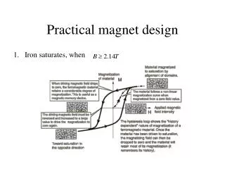
Cooling • Coil thermal analysis was presented at Collaboration meeting in June. • We discovered that a separate pump / chiller would need to be located between magnet and site water, so pressure drop can be higher than site pressure • Water temperatures fixed at 20 C supply / 60 C return. • Conductor type has been fixed.
Hall A Infrastructure • Hall A LCW Water System: • 500 GPM • 250 psi • 80-85 F supply / 110 F return • Seperate Moller magnet cooling system is required • Must isolate local water from site water to prevent activated water getting topside • Will include chiller to reduce LCW supply to 15-20 C and maintain to within a few degrees • Will supply cooling to upstream torus, hybrid, and collimators. • Hall A Power • Currently 0.86 MVA available • Best guess now is Hybrid alone will use 775 kW • Additional substation and power drops being installed for 2 MVA • Crane • 20 Ton capacity • Sufficient for assembling coils into support structure and loading into vacuum vessel • Combined toroid + vacuum vessel might be above 20t, but no plans to move them together
Hall A Infrastructure LCW Water (currently necked down from ~8” to ~4”) Junction box at existing power penetrations Existing power New power penetrations Left: Power drops from surface transformer, located at the upstream end of Hall A, beam-right. Right: penetrations (red arrow) for second surface transformer, and LCW lines. These will be converted to continuous large pipe (~8”) all the way to the floor of the hall.
1. Create a composite beam that represents the geometry of the coils (copper + GFRP) 2. Simulate that beam to determine the deflection under simple boundary conditions Filler: “Generic GFRP”; E=49 GPa 3. Use linear elastic model to determine effective stiffness, Eeff Eeff = 89.5 GPa This stiffness will be used in forgoing studies to represent the coil as a homogeneous material
Previous Analysis Fixed Spine Load Path: Coil Blocks Plates Strongback 12.9 deg from vertical – 0.359 mm No Contact between coil and clamp plate No Contact between coil and strongback Fixed Ends, Thickened Spine Horizontal: 3.73 mm 12.9 deg from vertical: 1.14 mm Horizontal: 0.354 mm
Updated carrier to avoid particle tracks Blue = Moller electrons – Must be avoided OLD, Z=13.7 m OLD, Z=11.4m NEW, Z=13.7 m NEW, Z=11.4m
Compare clamped ends to kinematic 6-strut support X + Y Phi + Z X + Y Note: Both end pins co-axial. All 3 pin axes intersect predicted CG of coil+carrier assembly
Includes equivalent homogenous coil, side-plates, and bolted connections • Bolts are 7075-T6. Combination of ½” and ¾” with 27 ft-lb and 82 ft-lb torque, respectively (k=0.2) • Friction between bolted surfaces is 0.5 25.8 deg from vertical: 2.08 mm Horizontal: 2.41 mm
Horizontal orientation, Factor of Safety (showing areas between FoS = 2 and 50) FoS for all areas is well above 2, except for the near strut pins. The strut pairs at either end should therefore be mounted non-coaxially, and oriented such that they share the gravity and toroid forces
Deflection Plot (Max = 0.182 mm) Stress Plot (Max = 23 MPa) Yield strength depends on specifics of composite and type of stress Most likely shear stress will need to be compared with delamination strength of GFRP or epoxy – copper bond
Designed to have coils installed from above Coil positions independently adjustable w.r.t. this frame Frame is bolted to stiff top plate of vacuum enclosure, hangs inside
BASELINE 7 carrier end faces fixed End spider fixed, rigid First pass at analyzing Frame: 3 main loading conditions On Floor Hanging Fixed 6 top beam nodes Beam Elements Solid Elements Fixed 2 bottom end surfaces Fixed 2 top end surfaces
Baseline deflection Hanging deflection • Why are the floor and hanging deflections so similar? The main difference between the models is that with the hanging condition, the upper z-beams are supported along their length, while for the floor condition, only the frame ends are supported. Looking at the reaction forces for the hanging case, we see that the vertical load carried by the z-beams is more than an order of magnitude less that that supported by the ends. Beam rxn= (2.88+2.47)e3 N = 545 kgf End rxn = (3.51+3.44)e4 N = 7085 kgf Hanging reactions
Hanging • Right: The highest stress was seen at the DS end of the hanging condition. At 92.6 MPa, it is well below the yield strength of 6061-T6 (275 MPa) but is still an area of concern. Because the mesh size here is relatively coarse (compared to salient dimensions of the parts), further studies should refine the mesh in these areas. • Left: A look at the strain at the DS end shows a great deal of twisting on the fingers and heptagon supports. Since these members transfer the coil end support conditions (i.e. slope) to the frame, reducing strain here will improve overall deflection. Increasing torsional stiffness should reduce twisting of the fingers • The beam stresses are very low (-3.0 – 2.3 MPa) in the hanging and floor-supported models. This is because the ends of the frame, where the coil load is borne, are directly supported by either the vacuuim chamber (hanging) or the ground (floor). It is likely some of these members can be made smaller / thinner.
Crane Fixed 4 top beam nodes Quick check of stresses in beams: Worst case while lifting with crane
Design Evolution Old in-vacuum design Old in-air design New (current) in-vacuum design. Vacuum chamber not shown.
Summary Coil Conductor and # cooling paths has been set, and work will continue to determine conductor splice locations and where services go. Design of chiller system awaiting further inputs from upstream torus and collimator simulations A realistic coil carrier has evolved over several iterations to avoid particle tracks and to utilize kinematic, adjustable supports. The resulting local coil deflection is < 3 mm. The coil support concept analyzed shows very little coil deflection due to internal "rounding" forces (< 0.25 mm). Further analysis will consider failure modes unique to composite structures. However, approximation using homogeneous material showed very low stresses in the coils. A realistic aluminum frame has been shown to contribute < 4 mm to the overall deflection of a set of 7 simple coil carriers with clamped end connections. This will be reduced when a model with complete carriers with kinematic supports is analyzed.
Size Comparison Airbus A320 General Atomics MQ-1 Predator Moller Hybrid Toroid, Support Structure, and Human Male
Coil Cooling • Assumptions for cooling analysis: • Pure water is used as cooling medium • Maximum water pressure will be limited to 17 atm (≈250 psi) • Inlet temperature 15 C, outlet temperatures from 50 – 80 C are explored • Fittings and bends not yet considered in pressure drop calculations • We are conducting ongoing discussions with JLab Hall engineers to determine cooling plant requirements and availability. J. Bessuille - MOLLER Spectrometer
Conductors • Hollow Cu conductors are available in a variety of standard sizes. I’m using data from Luvata; http://www.luvata.com/en/Products--Markets/Products/Hollow-Conductors/ From original TOSCA design J. Bessuille - MOLLER Spectrometer
Cooling Circuits • By setting an allowable temperature rise, we determine the required coolant flow rate. Each conductor has a different electrical and hydraulic resistance, both of which contribute to the pressure drop. • For a given conductor and temperature rise, we can look at the pressure drops that are realized from splitting each pancake into different numbers of cooling paths. Setting a limit on the pressure allows to establish the optimal (minimum) number of cooling circuits for a given configuration. J. Bessuille - MOLLER Spectrometer