Download

1 / 16
160 likes | 316 Views
TAGGER MAGNET DESIGN . Presented by Tim Whitlatch. Tagger Area. Permanent Magnet. North Wall. AC ducts. Vacuum gages and pump. Beam Current Monitor. Photon Beamline. Beamline encasement to Hall D. Quad. Radiator. Vacuum Chamber. Electron dump. Tagger Magnet. Truck ramp entrance.

E N D
TAGGER MAGNET DESIGN Presented by Tim Whitlatch Hall D Tagger Magnet Design Review July 10, 2009
Tagger Area Permanent Magnet North Wall AC ducts Vacuum gages and pump Beam Current Monitor Photon Beamline Beamline encasement to Hall D Quad Radiator Vacuum Chamber Electron dump Tagger Magnet Truck ramp entrance Shielding Hall D Tagger Magnet Design Review July 10, 2009
Tagger Components Preloaded threaded rod Vacuum chamber Vacuum Chamber supports Magnet steel Hodoscope frame attach points Coils Tagger support stands Tagger strong back Hall D Tagger Magnet Design Review July 10, 2009
Tagger Cross-Section • Adjustment cartridges use wedge type for vertical • Sliders for X-Z • +/- 1cm horizontal plane adjustment • +/-9mm vertical adjustment (standard part) • Each piece under 25 tons • Provision for porta-power for alignment • Vacuum chamber and pole form integral vacuum space Adjustment cartridges Hall D Tagger Magnet Design Review July 10, 2009
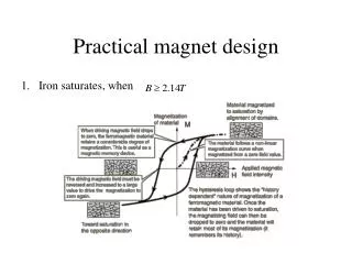
Magnet Cross-Section from Yang’s TOSCA (early version) Rowgoski contour all edges Gap machined to within ±.004 inches • All steel 1006 annealed Hall D Tagger Magnet Design Review July 10, 2009
Vacuum Chamber Support Support tubes Vacuum Chamber O-ring Support rods Window opening Support rods Window opening 45mm x 11.2 m Hall D Tagger Magnet Design Review July 10, 2009
Vacuum Chamber Beam O-ring groove along entire edge, top and bottom Skin, 0.25 inch plate Photon beam tube 12GeV electron beam exit opening Additional port for mag field probes both ends (location TBD due to synchrotron radiation) Add vacuum pumping port (not shown) Stiffening ribs 1 inch plate Hall D Tagger Magnet Design Review July 10, 2009
O-ring Groove (3/8) Generous Radii (1.3 in) for better sealing Support features Thicker flange for radius of o-ring groove Port for mag field probes both ends Beam tube Thin window Add pumping port Beam Hall D Tagger Magnet Design Review July 10, 2009
Vacuum Seal Details Support rod Coil Upper pole Vacuum Chamber back wall 30mm gap O-ring Lower pole Pole tip Hall D Tagger Magnet Design Review July 10, 2009
Vacuum Chamber Exit 45mm x 11.2 m window opening (thin window) 25 x 4.5 cm 12GeV electron beam opening 2.5 cm thick flange Hall D Tagger Magnet Design Review July 10, 2009
Magnet Coils • 12 by 7 cu/epoxy matrix. • 11 mm sq cu • 7 mm water path • 1.5 T 220A 105V • 1.8 T 366A 200V Coils 6.509 m 548 mm Hall D Tagger Magnet Design Review July 10, 2009
Coils Connections • Magnet Coils Electrical • Series • 1.8 T 366A 200V • 0.52 ohms Klixons and electrical flag connections needed Plexiglass shield for safety • Magnet Coils Cooling • 28 parallel circuits LCW • 34GPM • 8°C∆T • 6.5 ft/sec Tubes brazed together to form series circuit Hall D Tagger Magnet Design Review July 10, 2009
TaggerSupport Strongback Hodoscope attach points Adjustment cartridges Vacuum Chamber supports Base stands I-beam strongback 3-point adjustment ±9mm vertical adjustment ±1cm x-y adjustment Vacuum chamber support Stands grouted in place after alignment Final magnet alignment after install Hall D Tagger Magnet Design Review July 10, 2009
Use optical means to determine relation between pole edges and fiducials on each slab within 50 microns Laser tracking fiducial targets on tagger magnet to position relative to monuments within 40 microns Tagger Alignment Targets visible after install on upstream end Optically sight pole edges
Status of 3D Model • Magnet mostly modeled (needs coil support features) • Coil attach and layout needs to be complete • Vacuum chamber needs flange and window attach features • Support stands and adjustment mechanisms need more detail • Need to add jacking and alignment features to magnet steel Hall D Tagger Magnet Design Review July 10, 2009
What Needs to be done? • Finalize analysis on vacuum chamber and stand • Finalize hodoscope attachment • Analyze magnet support structure • Complete coil support design • Complete coil electrical/cooling design • Finalize tagger spec and SOW • Produce complete design drawings for tagger components • Procure/manufacture components • Detail installation procedure • Write analysis tech note (pressure system and structural) • Perform ES&H detailed analysis • Develop detailed plan for mapping • Thin window design • Look at ¼” o-ring Hall D Tagger Magnet Design Review July 10, 2009