Download
1 / 38
470 likes | 826 Views
Fire Physics, Nomenclature, and Modeling. An Educational Program to Improve the Level of Teaching Risk-Informed, Performance-based Fire Protection Engineering Assessment Methods. Fire Physics, Nomenclature, and Modeling.

E N D
Fire Physics, Nomenclature, and Modeling An Educational Program to Improve the Level of Teaching Risk-Informed, Performance-based Fire Protection Engineering Assessment Methods
Fire Physics, Nomenclature, and Modeling Focus is on internal/enclosed fire situations. Aspects important to NPP applications are emphasized. There is one Significant Fire Event Every 10 Reactor Years. Arthur Ruggles, UTNE
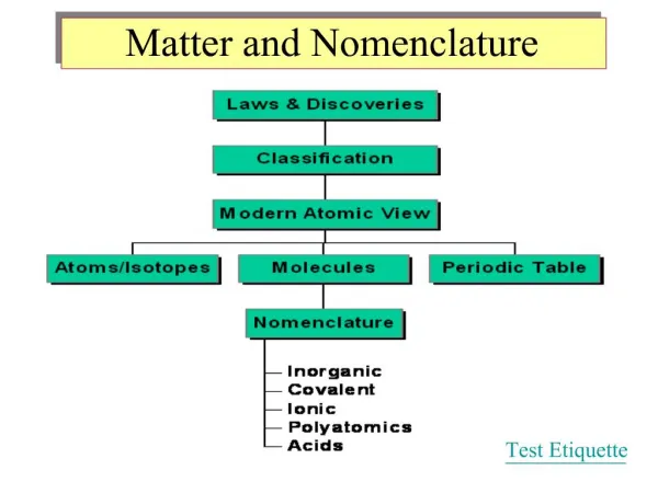
Outline of Material • Basics of Fire Modeling-Intro to Concepts • Definitions for phenomena • Energy release rates and energy release vs. time • Combustion efficiency • Mass loss rate • Flash-over • The Axi-symmetric plume • Enclosure flows • Smoke filling and combustion products
Philosophy of Presentation • The fire and fire induced plume drives the simulation-these physics are presented first. • The fire responds to feedback from the enclosure such as reflected heat from walls, or restricted air/oxygen inflow. • Relatively simple transport models and empirical models are introduced to develop understanding and intuition. • A few parameters important to Nuclear Power Plant (NPP) Probabilistic Risk Assessment (PRA) are presented.
Fire and Fire Plume Attributes Continuous Flame Height-combustion and thermal energy addition occurs in the flame Intermittent Flame-flame is varying in time and position in this region Mean Flame Height-time and position average for flame height needed for steady state model development, this is where energy addition due to combustion ends, and a buoyancy driven plume begins. Plume-buoyancy due to hot gasses from fire balanced by shear and mixing with entrained air to form a vertical flow of air and combustion gasses in the “plume”. Momentum balance used to define plume mass flow and diameter are considered later.
Context of Fire and Plume to Enclosure Fire Dynamics Fire drives the energy addition and hot gas production that causes the plume and creates hazard to humans via smoke inhalation and heat exposure. Mass flow in plume determines smoke filling rate in enclosure. Temperature in plume is important to buoyancy drive for flow into and out of the enclosure openings. Air/oxygen inflow often limits fire progression in enclosures. Fire progression, which involves heating and vaporization of adjacent fuel, determines energy release versus time, and fire duration.
Approach to Fire and Plume Modeling Energy release rate models-empirical. examine approaches to measurement and conventions for use. Mass Loss rate models and burn efficiency-empirical. examine approaches to measurement and conventions for use. Mean flame height models-empirical. measurement method and interface with plume parameters. Plume models, including plume mass flow, temperature and diameter-mechanistic. mass, momentum and energy balance leading to plume models. These are related to buoyancy driven flows from thermal science. Models developed for the plume are quasi-steady.
Empirical Model Development is based on Experimental Data Mass loss rate-mass versus time Mass flow in plume-mass flow measurement with plume capture in hood Oxygen content-oxygen meter, air is normally 23% oxygen by mass. Plume temperature measurement-RTDs or Thermocouples Combustion efficiency-mass flow with mass loss rate, oxygen content and temperature used to infer this quantity. Temperature
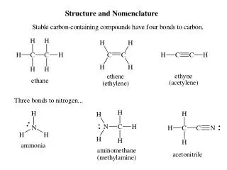
Energy Release Rate, Mass Loss Rate, Heat of Combustion and Heat of Gasification. Mass Loss Rate: The rate of fuel mass lost, Kg/s, some of which will combust, and some of which is gasified but does not combust. Combustion Efficiency: Ratio of effective (actual) heat of combustion in the fire over the complete heat of combustion, g. Heat of Combustion: Energy released per unit mass of fuel. There is effective heat of combustion, DHeff , which is equal to the combustion efficiency, g, times the complete heat of combustion, DHc . Heat of Gassification: Gases combust in fires. Some portion of the energy released from the fire must go back into gasification of liquid or solid fuels, DHg.
Energy Release Rate or Heat Release Rate The Heat Release Rate (HRR) is the total energy per unit time released by the fire. Units of KW are usually used in fire literature for power, so the HRR is usually given in KW. This definition of the HRR assumes the heat of combustion includes the energy required to gasify the fuel. In most cases 70% to 80% of the fuel combusts, placing g between 0.7 and 0.8.
Pool Fires • These fires are fairly common, machines with lube oil or transformer oil are dyked. • Dyked area determines the pool fire area, which determines heat release rate. • Lube oil or transformer oil inventory will fit in dyke by design. • Do not put tools and components inside the dyke during component service.
Pool Fires: Constant HRR Large pool fire mass loss rate per unit area, , is larger than that for smaller pool fires. An approximation for smaller pool fire mass loss rate is provided below, where the parameter kb is derived from data. The diameter of the fire, D, may be the diameter of a circle of equivalent area when the pool shape is not circular.
HRR and mass loss data per unit area for Common Combustible Materials: SFPE Handbook MATERIAL Mass Loss DHc kb(m-1) Polyethelene 0.026 kg/m2s 43.6 MJ/Kg Polypropolene 0.024 43.4 Kerosene 0.065 44.1 3.5 Gasoline 0.062 44.2 2.1 Transformer oil(s) 0.025-0.030 44.8 0.7 Polystyrene 0.034 39.2 Methanol 0.025 20 infinite Polyurethane foams 0.021-0.027 23.2-28.0 PVC 0.016 16.4 Teflon 0.007 Kg/m2s 4.8 MJ/Kg
Example Pool Fire Diesel for emergency generators is compromised by a 40 year old fitting Failure. Approximately 90 gallons are released into an area 3m by 4m. The combustion efficiency is near 0.75, evaluate the heat release rate and duration of this fire. Assume this is an unrestricted (open) fire.
Fire Progression in an Enclosure, Time Varying HRR Ignition: self sustained combustion begins, PRA may provide list of ignition sources and probability of occurrence. Growth: Fire grows, smoke layer forms and descends, temperature in smoke layer increases, and fire radiative flux increases. Flashover: Smoke layer/upper gas layer reaches 500F to 600F, and radiation from smoke layer and fire supports rapid fire spread to entire enclosure. Fully Developed fire: Air/oxygen limited combustion in enclosure. Ignition
HRR versus Time • Experiments with common fuel sources provide heat release rate versus time. • NPP fuel sources include cable insulation, paint, and various fluids (e.g., lube oil, transformer oil, solvents, fuel). • The HRR, along with fire base diameter, provide information on mean flame height. • HRR, flame height and fire base diameter allow quantification of the plume.
Fire Growth Phase: HRR=at2 • For Design Purposes, the growth phase is important since this is when protection and response systems should intervene. • Some values for a: 1/8 inch plywood wardrobe with clothes (.86); Easychair 23Kg (0.19) • “Fast” growth for a greater than 0.047. • “Slow” growth for a less than 0.003. (NFPA 204M)
Flame Height Modeling • Dimensionless groups used in natural convection flow appear in empirical models. L is flame height, D is fire diameter at base.
The Plume Above the Flame • The buoyancy in the plume above the flame is fixed if density is taken linear with temperature, and thermal losses are neglected. • Plume model involves a balance of buoyancy with momentum losses due to mixing with adjacent air. • Mixing also cools the plume average temperature, and increases the plume mass flow.
Note that average of products is generally not equal to the product of averages.
Homework 1 Solution: The first two steps follow almost exactly the sequence of the example earlier in the notes. Note that the oil evaporates more slowly than the diesel, but the heating value per unit mass for Diesel and the transformer oil are similar.
NRC has these Models Coded into Spread Sheets Available on-line for Free! These spreadsheets are in use now at for NPP fire safety assessment.
Plume Model Assumes Point heat source at Z=0. floor b Zo Virtual Fire at Virtual Origin
Enclosure Dynamics using Two Zone Model Plume feeds hot gases to hot layer. Hot layer fills enclosure and alters pressure distribution from that outside. Differential pressure drives flow into and out of the enclosure through openings. Flow into enclosure may limit oxygen availability for fire (ventilation controlled fire).
Cables in Trays and Conduit are all over the Plant. Often smaller diameter cables for instrumentation are suspended in trays. Time to loss of cable function is modeled in fire progression and plant response. PRA may include cable integrity predictions. (NUREG 1805)
Pressure Differences Drive flow Into and Out of Enclosure Fire Induced Hot Layer Alters Pressure Gradient In Enclosure Z+ Neutral Line Z- Hn Hd Neutral Pressure at Hn Density Change at Hd Define z relative to Neutral Plane
Pressure Differences can be related to Hot Gas Temperature, Hot Gas Layer Height, and Height of Neutral Pressure
Mass flow is reduced to account for some flow physics not captured in Isentropic Bernoulli Model.
Position of Neutral Pressure Plane is established using the Mass Balance Mass flow into the enclosure must equal the mass flow out of the enclosure. If the enclosure has only one opening, then the Neutral pressure plane will cut through that opening, allowing both inflow and outflow through the same opening. Neutral Pressure Plane door Note Velocity Profile for Inlet Flow is not Linear, Pressure Profile is linear, Velocity goes as Square root of Pressure for tall openings.
Flows Through Openings are Modeled using Form Losses And Modified Bernoulli Equation for Horizontal flow In Nuclear, Mechanical and Civil Engineering Upstream Flow is near zero, and downstream flow is also near zero, with maximum flow kinetic energy developed in the opening (actually just downstream of the opening), and later lost (actually thermalized via turbulence and shear), so our model reduces to:
Cfast is a Two Zone Fire Modeling Code that was Subjected to Verification and Validation (V&V) for NRC The code is general purpose, architectural enclosure fire modeling code developed by NIST The code has a primitive GUI, and solves the equations we just covered, so a fire progression can be modeled. The output is available in tables, or can be examined graphically using a package called Smokeview. Validation in this case means the code was run to predict experimental data from situations representative of a NPP. The predictions were compared with the test data, the outcomes reviewed, and published. The code was presumed to be Verified from previous examinations and tests during the development by NIST.