TRAINING AGENDA
260 likes | 510 Views
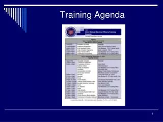
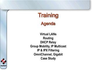
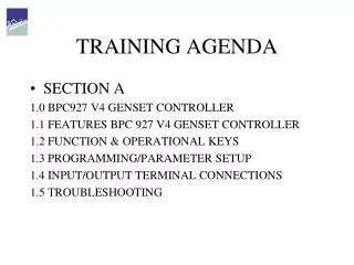
TRAINING AGENDA. SECTION A 1.0 BPC927 V4 GENSET CONTROLLER 1.1 FEATURES BPC 927 V4 GENSET CONTROLLER 1.2 FUNCTION & OPERATIONAL KEYS 1.3 PROGRAMMING/PARAMETER SETUP 1.4 INPUT/OUTPUT TERMINAL CONNECTIONS 1.5 TROUBLESHOOTING. 1.0 BPC927 V4 GENSET CONTROLLER. 1.0 BPC927 V4 GENSET CONTROLLER.

TRAINING AGENDA
E N D
Presentation Transcript
TRAINING AGENDA • SECTION A 1.0 BPC927 V4 GENSET CONTROLLER 1.1 FEATURES BPC 927 V4 GENSET CONTROLLER 1.2 FUNCTION & OPERATIONAL KEYS 1.3 PROGRAMMING/PARAMETER SETUP 1.4 INPUT/OUTPUT TERMINAL CONNECTIONS 1.5 TROUBLESHOOTING
1.0 BPC927 V4 GENSET CONTROLLER BACK VIEW
1.0 BPC927 V4 GENSET CONTROLLER • DO & DON’T’S • >>Do not disturb factory setting of controller. • >> Do not change wiring loop / connections. • >> Before fault handling observe LCD displays on the unit and follow procedure as recommended.
1.1 FEATURES BPC 927 V4 GENSET CONTROLLER • Salient Features - Suitable for1phase/3phase Genset applications - Suitable for 12 & 24 V Engine supply systems - Common for Manual / Auto / Remote start operation of Genset. - Field settable for authorized parameters - User friendly as it provides visual indications of warnings , alarms and system faults - Designed for continuous monitoring in both Idle and running condition of the Gen set
1.1 FEATURES BPC 927 V4 GENSET CONTROLLER • MAINS & GENSET PARAMETER’S MONITORING AND DISPLAY • GENSET SAFETY • AMF LOGIC • ADD ON FEATURES • COMMUNICATIONS • EVENT & OPERATING LOGS • FUEL LOGS
1.2 FUNCTION & OPERATIONAL KEYS SCROLL UP SCROLL DOWN COMMON ALARM LED HORN ACK BUTTON START BUTTON MODE BUTTON STOP BUTTON FRONT VIEW
1.2 FUNCTION & OPERATIONAL KEYS • Function of keys – in normal conditions of ‘Sleep ‘ and ‘ Ready ‘ . • key to enter Programming mode/Acknowledge Alarms. • For manual START. • For manual STOP. • Used to change the MODE between Manual, Auto & Test • Used to change load from Genset to Mains • Used to change load from Mains to Genset
1.2 FUNCTION & OPERATIONAL KEYS • Key Functions in ‘Running ‘ condition • - To stop the set manually when engine is started in manual mode Press the button again for immediate stop • Acts like Emergency stop when engine is running in Auto mode
1.3 PROGRAMMING/PARAMETER SETUP Key functions in Programming modeEnter • To enter programming mode by keep pressing key for 20 secs • When the unit enters set-up mode the top LCD will show “Setup” and optionally request a PIN number if this option is enabled. • Changes from column to item to value editor. • Used to select previous column, item or to increment value • Used to select previous column, item or to decrement value • Changes from item to column & exit set up mode. • Used to accept the value changes.
1.3 PROGRAMMING/PARAMETER SETUP Key functions in Programming modeEnter • Setup mode automatically terminates if no button in pressed for 60 seconds, or when you press the button with the column headers list visible.
1.3 PROGRAMMING/PARAMETER SETUP Programming Mode • programming mode by pressing key for 20 secs • When the unit enters set-up mode the top LCD will show “Setup” and optionally request a PIN number if this option is enabled. • Lets say, PIN is 123, Press two times, & then by pressing once, 100 will appear on screen. • Now Press once to move the cursor to middle digit. Now by pressing twice, 120 will appear on screen. • Now Press once to move the cursor to RHS digit. Now by pressing thrice, 123 will appear on screen.
1.3 PROGRAMMING/PARAMETER SETUP Programming Mode • By pressing key once, the Programming “Setup” will be displayed on the LCD Screen. Now various setup like System, Engine, Timers etc will get displayed in a vertical array. • Press & to select the desired setup sub menu & then press to open the desired sub menu for editing the associated parameters. • Press & to select the sub menu’s desired parameter & then press to open the sub menu’s desired parameter for editing.
1.3 PROGRAMMING/PARAMETER SETUP Programming Mode • Press & to increase or decrease the parameter value respectively. • Press to accept & save the updated parameter value. • Follow this procedure for the rest of the desired parameter’s updations / change etc. • After updations / changes , Press once to return to initial setup screen. • Now, Press once for saving the various updations & exiting from the programming mode. • It is recommended to follow the factory setting chart for various updations. Failure to this clause will affect the product warranty.
1.3 PROGRAMMING/PARAMETER SETUP TYPICAL LCD MESSAGES ( ENGINE) :
1.3 PROGRAMMING/PARAMETER SETUP • TYPICAL LCD MESSAGES (ELECTRICAL):
1.3 PROGRAMMING/PARAMETER SETUP CONFIGURABLE INPUTS : • Fire Alarm • Canopy Door Open • Belt Broken • Bypass 5. Engine Temp 2
1.3 PROGRAMMING/PARAMETER SETUP • PROTECTION AND SIGNAL OPTIONS ++ SPEED >> IN CASE OF DG SETS PHASE – NEUTRAL FROM ALTERNATOR ++ PRESSURE >> OIL PRESSURE SENSOR OIL PRESSURE SWITCH OIL PRESSURE SENSOR + SWITCH ++ WATER/ CYL HEAD >> SENSOR TEMPERATURE ++ RAD. WATER LEVEL >> SPECIAL SENSOR ++ FUEL LEVEL >> FUEL LEVEL GUAGE ++ BATTERY VOLTAGE >> BATTERY ++ EXCITATION >> WL – POINT OF CHARGING ALATERNATOR ++ POWER SUPPLY >> DIRECT FROM BATTERY TERMINALS
EMS927V4 AMF Genset Controller - Speed Inputs and Outputs + Comms A B Com 1.4 INPUT/OUTPUT TERMINAL CONNECTIONS CT2 CT3 J4 CT1 J5 • Installation & wiring J2 J1 J6 J3
1.4 INPUT/OUTPUT TERMINAL CONNECTIONS V4 SOCKET DETAILS • J1- COMMUNICATION/DATA PORT • J2- DC POWER SUPPLY • J3- SPEED INPUT • J4- ALTERNATOR AC INPUT • J5- MAINS AC INPUT • J6- I/O PORT • CT1...3- CURRENT TRANSFORMER’s
1.5 TROUBLESHOOTING PROCEDURE TO BE FOLLOWED FOR FAULT HANDLING >> OBSERVE DISPLAY ON THE LCD DISPLAY >> REFER TO THE TROUBLE SHOOTING READY RECKNOR >> STUDY UNIT SET UP DATA / CONFIGURATION DATA >> TAKE APPROPRIATE CORRECTIVE ACTION >> CLEAR & RESET THE ALARM >> ENSURE ENGINE IS RUNNING IN NORMAL CONDITION