Advanced Detector Systems for MODS Spectrographs at the Large Binocular Telescope
This paper presents the detector plan for the four cameras of the MODS (Multi-Object Double Spectrograph), a critical component of the world's largest optical telescope, the Large Binocular Telescope (LBT). The initial deployment will utilize 4K x 4K detectors, with a custom 8192 x 2880 detector planned for future upgrades. A traditional optical design, featuring a decentered paraboloid collimator and Schmidt camera, efficiently manages spectral data across a broad wavelength range. The design optimizes throughput and minimizes costs while providing essential astronomical functionalities, including full multi-slit capability.

Advanced Detector Systems for MODS Spectrographs at the Large Binocular Telescope
E N D
Presentation Transcript
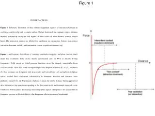
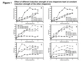
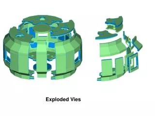
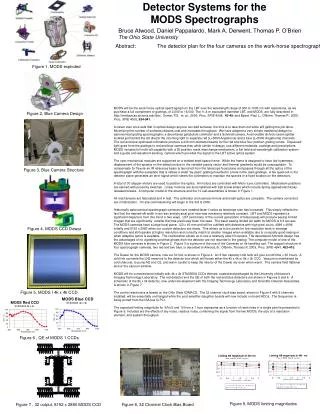
Detector Systems for the MODS Spectrographs Bruce Atwood, Daniel Pappalardo, Mark A. Derwent, Thomas P. O’Brien The Ohio State University Abstract: The detector plan for the four cameras on the work-horse spectrograph of the worlds largest optical telescope, the Large Binocular Telescope, is presented. The two cameras of MODS 1 will be outfitted for initial deployment in November, 2006 with 4K x 4K detectors processed by the University of Arizona Imaging Technology Laboratory. A custom run of 8192 x 2880 detectors is in the planning stages. These larger detectors will be used for MODS 2 and retrofits to MODS 1. The Dewar and electronics design are outlined. Projections of the limiting magnitude for the completed spectrograph at S/N=5 and 10 are given. Figure 1, MODS exploded MODS will be the work-horse optical spectrograph on the LBT over the wavelength range of 300 to 1000 nm with resolutions, as we purchase a full compliment of gratings, of 2,000 to 16,000. The 11.8 m equivalent diameter LBT, and MODS, are fully described in http://medusa.as.arizona.edu/lbto/, Osmer, P.S. et. al., 2000, Proc. SPIE 4008, 40-49, and Byard, Paul L., O’Brien, Thomas P., 2000, Proc. SPIE 4008, 934-941. A clever man once said that in optical design anyone can add surfaces, the trick is to take them out while still getting the job done. Minimizing the number of surfaces reduces cost and increases throughput. We have adopted a very simple traditional design for astronomical grating spectrographs: a decentered paraboloid collimator and a Schmidt camera. A removable dichroic beam splitter located just behind the slit directs the incoming light to separate red (L>5000 Angstroms) and a blue (L<5000 Angstroms) channels. The red and blue optimized collimators produce a 230 mm diameter beams for the red and blue four-position grating turrets. Dispersed light goes from the gratings to red and blue cameras that, while similar in design, use different materials, coatings and prescriptions. MODS includes full multi-slit capability with a 25 position mask interchange mechanism, a flat field and wavelength calibration system and a guide and wavefront-sensing camera which provides the signal to the LBT active optics system. The opto-mechanical modules are supported on a welded steel space frame. While the frame is designed to have low hysteresis, displacement of the spectra on the detectors due to the variable gravity vector and thermal gradients would be unacceptable. To compensate for flexure an IR reference beam is launched from the telescope focal plane and passes through all the optics of the spectrograph with the exception that is strikes a small “by-pass” grating mounted in a hole in the main gratings. A Ge quad cell in the detector plane generates an error signal which steers the collimators to maintain the spectra in a fixed location on the detectors. A total of 30 stepper motors are used to position the optics. All motors are controlled with Micro-Lynx controllers. Mechanism positions are sensed with proximity switches. Linear motions are accomplished with ball screw slides which include spring-applied/electrically-released breaks. A computer model of the structure and the 10 sub-assemblies is shown in Figure 1. All mechanisms are fabricated and in test. The collimator and camera mirrors and small optics are complete. The camera correctors are in fabrication. On site commissioning will begin in the 3rd Q 2006. Historically astronomical spectrograph cameras have needed faster f-ratios as telescope size has increased. This simply reflects the fact that the desired slit width in arc-sec and physical pixel size was remaining relatively constant. LBT and MODS represent a significant departure from this trend in two ways. LBT (and many of the current generation of telescopes) will produce seeing limited images that are significantly smaller that has previously been the case. The basic seeing limited slit width for MODS is 0.6 arc-sec. The MODS cameras have a large focal plane, 120 x 40 mm and will be outfitted with detectors with high pixel count, 4096 x 4096 initially and 8192 x 2880 when our custom detectors are ready. This allows us to bin pixels for low resolution work in average conditions and still operate at higher resolution and correctly match to smaller images when available due to unusually good seeing or when adaptive optics is available. The combination allows us to use a relatively slow f/3 camera. The decentered Schmidt design has the advantages of no vignetting and that ghosts from the detector are not returned to the grating The computer model of one of the MODS blue cameras is shown in Figure 2. Figure 3 is a picture of the one of the Cameras on its handling cart. The support structure of four spectrograph cameras, two red and two blue, is described in Atwood, B., O’Brien, Thomas P, 2003, Proc. SPIE 4841, 403-410. The Dewar for the MODS camera, now out for bid, is shown in Figure 4. An 8 liter capacity LN2 tank will give a hold time > 30 hours. A cold link connects the LN2 reservoir to the detector box which will house either the 4k x 4k or 8k x 3k CCD. Vacuum is maintained by cold charcoal, to pump N2 and O2, and warm zeolite to keep the interior of the Dewar dry even when warm. The camera field flattener lens is the vacuum window. MODS will be commissioned initially with 4k x 4k STA0500A CCDs thinned, coated and packaged by the University of Arizona’s Imaging Technology Laboratory. The red detector and the QE of both the red and blue detectors are shown in Figures 5 and 6. A schematic of the 8k x 3k detector, now under development with the Imaging Technology Laboratory and Scientific Detector Associates, is shown in Figure 7. The control electronics is based on the Ohio State ICIMACS. The 32 channel clock bias board, shown in Figure 8 with 8 channels installed, will be essentially unchanged while the post-amplifier daughter boards will now include on board ADCs. The Sequencer is being ported from the ISA bus to PCI. The expected limiting magnitude for S/N=5 and 10 from a 1 hour exposures as a function of read noise in a single pixel is presented in Figure 9. Included are the effects of sky noise, readout noise, combining the signal from the two MODS, the size of a resolution element, and system throughput. Figure 2, Blue Camera Design Figure 3, Blue Camera Structure Figure 4, MODS CCD Dewar Figure 5, MODS I 4k x 4k CCD Figure 6 , QE of MODS 1 CCDs Figure 9, MODS limiting magnitudes Figure 7 , 32 output, 8192 x 2880 MODS CCD Figure 8, 32 Channel Clock Bias Board