Download
1 / 48
480 likes | 596 Views
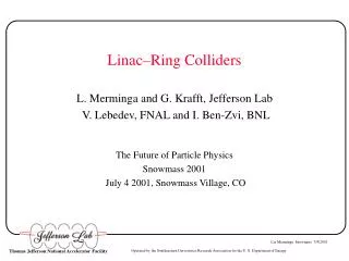
Linac–Ring Colliders L. Merminga and G. Krafft, Jefferson Lab V. Lebedev, FNAL and I. Ben-Zvi, BNL The Future of Particle Physics Snowmass 2001 July 4 2001, Snowmass Village, CO. Outline. Physics Requirements Two Scenarios Energy Recovery Linacs / The JLab IR FEL

E N D
Linac–Ring Colliders L. Merminga and G. Krafft, Jefferson Lab V. Lebedev, FNAL and I. Ben-Zvi, BNL The Future of Particle Physics Snowmass 2001 July 4 2001, Snowmass Village, CO
Outline • Physics Requirements • Two Scenarios • Energy Recovery Linacs / The JLab IR FEL • Linac – Ring Point Designs • Accelerator Physics Issues of Protons • Accelerator Physics Issues of Energy Recovery Linacs • Fundamental Luminosity Limitations • R&D Topics • Conclusions
Physics Requirements • Electron – proton colliders with the following requirements have recently been proposed as a means for studying hadronic structure: • Center-of-mass energy between 14 GeV and 100 GeV with energy asymmetry of about 1 – 6, which yields Ee=3 GeV to 10 GeV and Ep=15 GeV to 250 GeV • Luminosity at the 1033 cm-2 sec-1 level • Longitudinal polarization of both beams in the interaction region 50% –80%
Two Scenarios • Two accelerator design scenarios have been proposed: • ring – ring • linac – ring • Linac – ring option presents advantages with respect to • spin manipulations • reduction of synchrotron radiation load in the detectors • wide range of continuous energy variability • Feasibility studies were conducted at BNL (based on RHIC) and Jefferson Lab to determine whether the linac-ring option is viable. Self-consistent sets of parameters were derived • Rf power and beam dump considerations require that the electron linac is an Energy Recovery Linac(ERL)
Energy Recovery Linacs • Energy recovery is the process by which the energy invested in accelerating a beam is returned to the rf cavities by decelerating the same beam. • There have been several energy recovery experiments to date, the first one at the Stanford SCA/FEL. • Same-cell energy recovery with cw beam current up to 5 mA and energy up to 50 MeV has been demonstrated at the Jefferson Lab IR FEL. Energy recovery is used routinely for the operation of the FEL as a user facility.
The JLab 1.7 kW IRFEL and Energy Recovery Demonstration Wiggler assembly G. R. Neil, et al., “Sustained Kilowatt Lasing in a Free Electron Laser with Same-Cell Energy Recovery,” PRL, Vol 84, Number 4 (2000)
Energy Recovery Works Gradient modulator drive signal in a linac cavity measured without energy recovery (signal level around 2 V) and with energy recovery (signal level around 0).
Energy Recovery Works With energy recovery the required linac rf power is ~ 16 kW, nearly independent of beam current. It rises to ~ 36 kW with no recovery at 1.1 mA.
Benefits of Energy Recovery G. R. Neil, FEL Conference 1999, Hamburg Germany.
Benefits of Energy Recovery G. R. Neil, FEL Conference 1999, Hamburg Germany
Benefits of Energy Recovery • Required rf power becomes nearly independent of beam current. • Increases overall system efficiency. • Reduces electron beam power to be disposed of at beam dumps (by ratio of Efin/Einj). • If the beam is dumped below the neutron production threshold, then the induced radioactivity (shielding problem) will be reduced.
Proton Ring Polarized Electron Source Energy Recovery Electron Linac Electron Beam Dump Linac–Ring Schematic Layout Assume linac uses TESLA-style cavities at 20 MV/m and Q0~1x10¹⁰
Linac–Ring Collider Reasoning and Point Design 1 • Input parameters: Ee = 5 GeV and Ep = 50 GeV • Reasoning: • Set electron beam size at IP based on projected source performance • Set proton beam parameters at Laslett tuneshift limit • Determine number of electrons per bunch • Determine collision frequency
Electron Beam Parameters at the IP • Assume εn~ 60 μm at Q ~ 1.75 nC (Emittance dilution in linac will be addressed below) • At Ee = 5 GeV, εe= 6 nm • For β* = 10 cm, σe* = 25 μm (Round beams are assumed for electrons and protons)
Proton Beam Parameters • For Laslett tuneshift sets a limit on • We assume: • For εn,p = 2 μm (LHC, RHIC), β* = 10 cm => σp* = 60 μm and Np = 1 x 10¹¹ at the Laslett tuneshift limit.
Number of Electrons per Bunch Ne is limited by: • Beam-beam tuneshift of proton beam • For ξp = 0.004, Ne = 1.1 x 10¹⁰
Collision Frequency • Maximize fc subject to constraints: • Parasitic collisions • User requirements based on current understanding • Electron cloud effect • Assume bunch separation of 6.66 nsec or fc = 150 MHz
Luminosity of Point Design 1 Ie = 0.264 A Ip = 2.4 A fc = 150 MHz σe* = 25 μm σp* = 60 μm L = 6.2 x 1032 cm-2 sec-1
Point Design 2 • Input parameters: Ee=5 GeV and Ep=50 GeV • Cooling of protons is assumed • Electrons and protons have equal beam size at the IP • Electron beam parameters remain the same • This optimization yields: Ie= 0.264 A Ip = 2.4 A e* = 25 m p* = 25 m L = 2.1 x 1033 cm-2 sec-1
Point Design 3: The eRHIC Linac-Ring Scenario • Input parameters: Ee=10 GeV and Ep=250 GeV • Ie= 0.270 A Ip = 0.83 A e* = 33 m L = 1.14 x 1033 cm-2 sec-1 p* = 33 m fc = 56 MHz
Accelerator Physics Issues of Protons • Intrabeam scattering: Transverse Point design 1: τtr = 36 minutes Point design 2: τtr = 32 seconds • Intrabeam Scattering: Longitudinal Point design 1: τtr = 160 minutes@ σE/E=3e-3 Point design 2: τtr = 14 minutes @ σE/E=3e-3 • Collective Effects • Longitudinal mode coupling Np <6 x 10¹² • Transverse mode coupling instability Np <1.8 x 10¹²
Emittance growth of the electrons due to a single collision • A single collision disrupts the electron beam and causes emittance growth • Electron beam with degraded phase space has to be recirculated and energy recovered • Adiabatic antidamping can result in scraping and beam loss in the cryomodules • Therefore, amount of tolerable beam loss at the linac exit imposes a limit on tolerable emittance growth due to collision. This in turn imposes a limit on Np • In the small disruption limit: εn2 = ε0,n2 + (0.194 re Np)2 Np 1.5 x 10¹² ppb
Accelerator Physics Issues of ERLs • Source • Accelerator Transport • Beam Loss • Collective Effects • Single-bunch effects • Multipass, Multibunch Beam Breakup (BBU) Instabilities • HOM Power Dissipation
High Current Source of Polarized Electrons • High average current (~ 250mA), high polarization (~80%) electron source is a significant technological issue • State of the art in high average current, polarized sources: ~1 mA at 80% polarization [C. Sinclair, JLab] Hartmann, Sinclair et al., eRHIC Workshop, April 2000
acceleration energy recovery Linac Optics • Two beams of different energies must remain confined in the same focusing channel. A possible solution (I. Bazarov, Cornell University) for a 5 GeV ERL
Beam Loss • IR FEL experience: • Loss in the cryomodule 0.1 A (Radiation measurements) • Loss at wiggler entrance < 1 nA • Loss in recirculation arc 0.1 A (BLMs) At energies > 10 MeV, beam loss 0.1 A out of 5 mA (~60pC @ 75MHz)
Single-bunch Effects • Single-bunch, single-pass effects: limit bunch charge • Energy spread induced by variation of longitudinal wakefield across bunch For TESLA cavities, kloss~ 8.5 V/pC at σz=1 mm, the induced relative energy spread at 5 GeV is σE/E ~ 5 x 10⁻⁴ • Emittance growth induced by single-bunch transverse BBU Ne < 1.5 x 10¹¹ • Minimize strength of impedance source (SRF better!)
Multipass - Multibunch BBU Instabilities • Collective effects driven predominantly by high-Q superconducting cavities and can potentially limit average current • In a recirculating linac, the feedback system formed between beam and cavities is closed and instabilities can result at sufficiently high currents • Instabilities can result from the interaction of the beam with • transverse HOMs Transverse BBU • longitudinal HOMs Longitudinal BBU • fundamental accelerating mode Beam Loading Instabilities • Transverse BBU is the limiting instability
Transverse BBU (cont’d) • TDBBU*: 2d beam breakup code used for simulations • Simulations give threshold of ~ 230 mA • Typical growth rate of the instability is ~2 msecs. • Feedback (similar to B-Factories) may be possible (B-Factory bunch-by-bunch feedback at 4 nsecs works!) • Experiments in the IRFEL aim towards experimental verification of TDBBU *Developed by Krafft, Bisognano and Yunn
FEL BBU Experiment: Preliminary Conclusions • Threshold current in the IR FEL varies between 7 mA and 32 mA, under various beam and accelerator configurations • Under the nominal FEL configuration, threshold current is between 16 mA and 21 mA • For the nominal FEL configuration, TDBBU prediction is 27 mA agreement within ~40% • Observed optics dependence has not been quantified yet
HOM Power Dissipation • Power dissipated by the beam in HOMs, primarily longitudinal: depends on product of bunch charge and average current • For TESLA cavities, kloss ~ 8.5 V/pC for σz=1 mm and Iave = .264 A Pdiss ~ 8 kW per cavity • IR FEL: Iave = 5 mA, Pdiss ~ 6 W per cavity • Measurements of HOM power vs. bunch charge and bunch repetition frequency were carried out in the IRFEL
Measurements of HOM Power vs. Bunch Charge k||(1) = 1.4 V/pC + k||(2) = 8.0 V/pC k||total = 9.4 V/pC agreement within 15% k||URMEL= 11.0 V/pC
Conclusions from HOM Experiment • We observed the expected functional dependence of HOM power on bunch charge and bunch repetition frequency: PHOM Q2 fbunch • Loss factor for CEBAF cavities derived from measurements agrees with calculation (URMEL) within 15%
“Where have all the losses gone?” • The fraction of HOM power dissipated on cavity walls depends on the bunch length and increases with the HOM frequency, due to Q0 ~ f2 degradationfrom BCS theory • It can limit Iave and Ipeak due to finite cryogenic efficiency • A simple analytic model suggests that the fraction on the walls is much less than the fundamental mode load • Engineering studies on HOM absorbers are highly recommended
Beam-Beam Kink Instability • The beam-beam force due to the relative offset between the head of the proton bunch and the electron beam will deflect the electrons. The deflected electrons subsequently interact with the tail of the proton bunch through beam-beam kick. • The electron beam acts as a transverse impedance to the proton bunch, and can lead to an instability. • In the linear approximation, and disregarding the evolution of the wake within the proton bunch, a stability criterion has been derived [Li, Lebedev, Bisognano, Yunn, PAC 2001] • For the case of equal bunches and linear beam-beam force, chromaticity appears to increase the threshold of the instability [Perevedentsev, Valishev, PRST ‘01]. • The instability has been observed in numerical simulations [R. Li, J.Bisognano, Phys. Rev. E (1993)] during the beam-beam studies of linac-ring B-Factory. The code is presently being used to simulate unequal bunches and a nonlinear force. We also expect chromaticity to be beneficial in this case.
Fundamental Luminosity Limitations Luminosity vs. proton beam energy at the Laslett and beam-beam tuneshift limits, for two values of the Laslett tuneshift: 0.004 and 0.04. In both cases p=0.004
Fundamental Luminosity Limitations (cont’d) Luminosity vs. proton beam energy at the stability limit of the beam-beam kink instability (linear approximation: )
R&D Topics • High average current (~ 250mA), high polarization (~80%) electron source • State of the art in high average current, polarized sources: ~1 mA at 80% polarization [C. Sinclair, JLab] • High average current demonstration of energy recovery • Multibunch beam breakup instability • HOM power dissipation • Control of beam loss • Electron cooling and its ramifications on Laslett and beam-beam tuneshifts • Theoretical and if possible, experimental investigation of the beam-beam kink instability
Conclusions • Self-consistent sets of parameters has been developed for linac-ring colliders • Luminosities of several 1032 up to 1033 appear feasible • No accelerator physics showstoppers have been found. • Several important issues have been identified that would require focused R&D • ERL: Cornell University in collaboration with Jefferson Lab, is proposing a high average current (100 mA), high Energy Recovery Linac (5-7 GeV) for a next generation light source and is planning to address some of the technical issues with a smaller scale prototype (100 mA, 100 MeV) • PERL: Similar proposal is being pursued at BNL
ERL X-ray SR Source Conceptual Layout Courtesy I. Bazarov, PAC 2001
ERL Prototype We plan to begin work in the fall! 3.5 year construction, 1.5 year measurements Charge per bunch 77 pC Emittance, norm. 2* μm Shortest bunch length 100* fs Beam Energy 100 MeV Injection Energy 5 MeV Beam current 100 mA Courtesy I. Bazarov, PAC 2001
Example of Interaction Region Design Example of the interaction region design for * = 6 cm.