Download
1 / 17
170 likes | 406 Views
Analysis of high temperature polymer electrolyte membrane fuel cell impedance during break-in Søren Juhl Andreasen and Søren Knudsen Kær Department of Energy Technology, Aalborg University, Denmark. Outline. Introduction to HTPEM fuel cells Experimental setup Fuel cell control system

E N D
Analysis of high temperature polymer electrolyte membrane fuel cell impedance during break-in SørenJuhlAndreasenand Søren Knudsen Kær Department of Energy Technology, Aalborg University, Denmark
Outline • Introduction to HTPEM fuelcells • Experimentalsetup • Fuelcellcontrol system • Impedance system • Experimentalresults • Cellsexamined • Voltage vs. time • Impedance vs. time • Summary and outlook
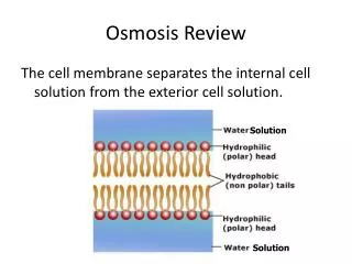
Introduction Hightemperature PEM fuelcells • High Temperature PBI based PEM Fuel Cell • Membrane polymer: PBI (polybenzimidazole) • Proton conductor : H3PO4 (Phosphoric acid) • Fuel cell temperature: 120-200 oC • Typical operating range:160-180oC • Advantages • Less complex polymer • CO tolerant up to 2-3% • No humidity control = Simple stack and system design • Cooling possible at all ambient conditions • Disadvantages • Lower cell voltage than LTPEM • Long start-up time because of high temperature • Liquid water should not e present 3
Status - HTPEM FuelCellBreak-in The initial hours of operation areusuallyknown as the ”break-in” time of the fuelcell Usuallyrecommendedbreak-in time is 0 to 100 hours, using a certaincurrentdensitypath, temperatures and stoichiometries, dependingonmanufacturer. Duringbreak-in an increase of fuelcellvoltage performance is typicallyexperienced. Break-in is costly and inconvenient to the stack/systemmanufacturer / integrator Betterunderstanding is requiredregarding the mechanismstakingplaceduringbreak-in in order to provide proper guidelines for optimal usage of HTPEM fuelcells. Only a few references areavailableregarding proper break-in / activation of HTPEM fuelcells, theyaremainlyrelated to pure hydrogen operation.
Typicalbreak-involtage performance Typical recommended break-in conditions for a HTPEM fuel cell: Constant ”low current” 0.2 A/cm2, 160oC operating temperature, operation for 10-100 hours
Experimentalsetup • HTPEM heated single cell assembly, straight flow channels • Two National Instruments based control systems: • Automated fuel cell control system (Labview) • Impedance measurement system able to superposition signals onto fuel cell current • Hardware: • Fuel Cell Control System • NI PCI 6401 AO DAQ card • NI PCI 6229 AI DAQ card • NI PCI 4351 AI DAQ card • TDI Power RBL 488 • Bürkert 8711 MFC H2 • Bürkert 8711 MFC CO • Bürkert 8711 MFC CO2 • Bürkert 8712 MFC Air • 230VAC controlled electrical heater • 2 Type T thermocouple (cathode/anode) • EIS measurement system • NI PCI 6259 DAQ card • Load signal switching relays
Break-inimpedance plot Selected MEAs: 4 MEAs from DPS: Dapozol G77 membranes (PBI) Varying catalyst loading Varying GDL thickness Varying polymer content in CL 2 MEAs from BASF: Celtec P2100 Celtec P1000*
BASF Nyquist plot - pre/postbreak-in Impedance behaviour: Both P1000 and P2100 cells show quite dramatic changes in most of the impedance spectrum, both in high, intermediate and low frequencies. Membrane resistance increases during break-in due to acid removal The main changes contributing to these changes are expected to be, acid reallocation i.e. the combined movement of acid into and away from the gas difusion and catalyst layer. Water content and production is also expected to play an important role and needs further investigation.
DPS Nyquist plot - pre/postbreak-in Impedance behaviour: Not as dramatic difference between pre and post break-in impedance comparred to BASF membranes due to different membrane types and production methods. Less changes are occuring at intermediate and low frequencies. Generally a slightly higher increase in membrane resistance is experienced. Only slight differences of the chosen variations in catalyst loading and polymer content in the catalyst layer, with the most promesing performance in the MEAs with the least PBI content in the CL
Real part of impedance vs. break-in time Real impedance behaviour: Small impedance changes occur at high frequencies during the first couple of hours of operation A steady drop in the real part of the low and intermediate frequency impedance is experienced during the first 10 hours of operation
Imaginary part of impedance vs. break-in time Imag impedance behaviour: The intermediate frequency imaginary impedance show changes that settle after 15-20 hours operation. Low frequency imaginary impedance does not shows significant changes related to break-in.
Real part impedance behaviour 1kHz: Both BASF MEAs show an initial short term change, followed by a more steady 1000 Hz real part impedance change due to changes in membrane resistance. The DPS MEA does not exhibit the initial ”fast” change in high frequency resistance. The variations in catalyst loading and PBI content in the catalyst layer does not seem to by affect the slope of the break-in impedance development.
Real part impedance behaviour: Slightly faster settling of the DPS fuel cells MEAs is seen at this frequency, which may well also be attributed to the differences in not only phosphoric acid content in the GDL, but also the GDL type. The BASF GDL being woven and the DPS carbon paper type.
Imag part impedance behaviour: Both BASF MEAs have a characteristic 10-20% drop in imaginary part of the impedance after 10 hours. The DPS MEAs show a more stable behaviour during this time.
Summary and Outlook • Conclusions • Impedance changes occurring with different time constants are identified, from fast initial 1 hr decreases and increases to slower 20+ hr changes, all affecting fuel cell performance. • High frequency impedance decrease is primarily related to membrane resistance, and the presence of phosphoric in the catalyst. The changes are expected to be due to phosphoric acid re-allocation / water contribution. • Intermediate and low frequency impedance changes are expected to be related to the increased catalyst activity due to removal of phosphoric acid from the catalyst layer, more dramatic effect in the BASF MEAs, which initially show quite high content of phosphoric acid in the MEA and GDL, compared to the DPS MEAs that are post treated with phosphoric acid. • A quantitative analysis of the varying polymer content and the effect of catalyst loading on MEA performance has shown that higher polymer content in the CL requires longer break-in possibly due to not only more polyer present in the catalyst layer, but also phosphoric acid, blocking active areas. • Presence of high amounts of phosphoric acid in the MEA could block catalytic sites and cause problems with anode starvation (high anode potentials, and increased carbon corrosion), if high current densities are used in a very early stage of fuel cell lifetime. In turn this could decrease lifetime • Measuring selected impedances during break-in can be used as a guideline to determine proper break-in time. • Future work • The long term effects of operation with/without break-in should be examined. • Further tests should be conducted with reformate gas break-in, looking at the effects of water, CO, CO2 and residual fuel in the gas, and how it affects the break-in impedance. • Further detailed tests also using polarization curves and impedance measurements at different current densities should be examined.
Acknowledgements Ackowledgements The authourswouldlike to gratefully acknowledge the financial support from the EUDP program and the Danish Energy Agency for sponsoring the project :COmmercialBReakthrough of AdvancedFuelCells -(COBRA) Thank you!
Analysis of high temperature polymer electrolyte membrane fuel cell impedance during break-in SørenJuhlAndreasenand Søren Knudsen Kær Department of Energy Technology, Aalborg University, Denmark