Download

1 / 23
260 likes | 556 Views
Overview of Super-Harvard Architecture (SHARC). Daniel Glick – May 15, 2002 for V22.0480-002 (Dewar). SHARC. 32-bit DSP Optimized for I/O – DMA, rapid interrupt handling, dual-ported memory On-board floating point We will examine ADSP-2106x

E N D
Overview of Super-Harvard Architecture (SHARC) Daniel Glick – May 15, 2002 for V22.0480-002 (Dewar)
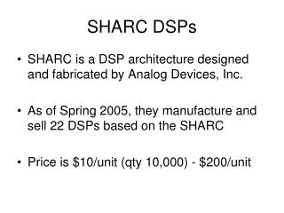
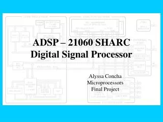
SHARC • 32-bit DSP • Optimized for I/O – DMA, rapid interrupt handling, dual-ported memory • On-board floating point • We will examine ADSP-2106x • Manuals are online at:http://www.analog.com/library/dspManuals/ADSP_2106x_SHARC_Users_Manual_books.html
Registers – General Registers • Register file • 16 40-bit registers • Each register can be interpreted as fixed point (R prefix) or floating point (F prefix) • Divided into two segments for context switching • Multiplier result register • 80 bits, accessible as three 32-bit registers
Registers – Addressing Registers • 16 sets of addressing registers, divided into 4 segments for context switching • Each set has: • Index • Modifier (offset from index) • Base (base of circular buffer) • Length (length of circular buffer)
Registers – System Registers • Program Sequencer Registers • 3 program counters (1 for each stage of pipeline) • 5 registers for branching (subroutines and looping) • System Registers • 2 32-bit mode registers • 3 registers for interrupt handling • Flags
Registers - Flags • Arithmetic status flag registers • ASTAT: reset after each operation • STKY: remains set until cleared • Same registers, different semantics for: • ALU ops • Multiplier ops • Shifter ops • Two user-defined 32-bit status registers
Registers – Context Switching • Alternate set of general, multiplier, and address registers • Each segment of registers can be separately switched between primary/alternate sets by setting a bit in the mode register
Data Formats • Integer • 32-bit word • In 40-bit register, stored in 32 MSBs • Floating-point • 32-bit (IEEE standard) • 40-bit (IEEE + 8 extra LSBs of mantissa) • 16-bit (11-bit mantissa + 5-bit exponent + sign bit)
Memory - Addressing • Word-based addressing • 16, 32, or 48-bit words • Two address buses • Data bus: 32-bit addresses • Program bus: 24-bit addresses • Can also be used to access data • Each bus has a Data Address Generator (DAGs)
Memory – Addressing (cont.) • Each DAG has eight sets of registers • Each set is: Index, Modifer, Base, and Length • Addressing modes: • Index + modifier • Index + immediate • (Index + modifier mod length) + base • For circular buffers
Memory – Word Alignment • Overlapping address spaces • 0x20000 – 0x3FFFF and0x40000 – 0x7FFFF point to same physical memory • Difference: accessing long words or short words • Long words • 48 bits on program bus, 32 bits on data bus • Short words • 16 bits on either bus
Memory – Physical Structure • Up to 512 KB of on-chip SRAM • Divided into two equal-sized blocks • Both can be accessed simultaneously, using both buses • External Memory • 32-bit addresses • Up to 4 gigawords
Instruction Set – Compute & Move • Arithmetic, multiple, shift, register move, load, store • Loads and stores can be explicit or part of a compute operation • Execution of each instruction can be conditioned on a flag
Instruction Set – Flow Control • JUMP and CALL to relative or absolute address • Can be conditioned on flags • Compute instruction can be conditioned on failure of jump condition, all within a single instruction word • CALLs and interrupts store return address to on-chip PC Stack • 30 levels deep • Triggers interrupt when 29 levels full
Instruction Set – Flow Control (cont) • DO UNTIL – looping • Condition can be flag • Condition can be loop counter register = 0 • Loop stacks, for nested loops • Loop counter stack • Loop termination address stack • Both 6 levels deep
Instruction Set – Multiple Compute • Dual add / subtract • Dual-result op: sum and difference of input regs • Parallel multiply / ALU • Simultaneously performs multiplication and ALU operation • All multiple compute ops limited to a specific subset of registers, to fit within 48-bit instruction word
Instruction Set - Miscellaneous • Set register bits • Access flow control stacks • IDLE: halt until interrupt • Flush instruction cache • CJUMP/RFRAME • C-style function prolog and epilog
Pipelining & Caching • Three-stage pipeline • Fetch • Decode • Execute • 2-way, set-associative, 32-instruction cache • Instructions are only cached if they conflict with a data read
Instruction Latency • One cycle latency on register context switch • One cycle latency on some writes to system registers • Delay flag in branch instructions • If set, two instructions following branch are executed • Loop exit test • Test value must be set two cycles before test
Interrupts • 32 interrupts • Descending priority from 0 to 31 • Can be individually or globally masked • Interrupt vector • 8 instruction words per interrupt • 3 external IRQs available
Interrupts - Handling • Interrupt is latched during processing • Cannot be re-triggered until processing is over • For some interrupts, status and mode flags are stored to on-chip status stack • Based on system option flag: • Either all interrupts are masked • Or all lower-priority interrupts are masked • Latency: for most interrupts, one instruction is executed after interrupt triggered
I/O • DMA • 10 channels • For each channel, three memory-mapped registers: • II – starting address base • IM – starting address modifier • C – number of words to transfer • Interrupts at end of transfer (C = 0)
Summary – Design Philosophy • CISC/RISC hybrid • Pipelined • Fixed-width instructions • Some instructions are complex, multi-cycle • Efficiency chosen over consistency/simplicity • Special instructions • Specialized registers • No consistent word size • Specialized buses