Download
1 / 34
400 likes | 704 Views
48.8mW Multi-cell InP HBT Amplifier with on-wafer power combining at 220GHz. Thomas Reed, Mark Rodwell University of California, Santa Barbara Zach Griffith, Petra Rowell, Miguel Urteaga , Mark Field, Jon Hacker Teledyne Scientific & Imaging, LLC treed@ece.ucsb.edu.

E N D
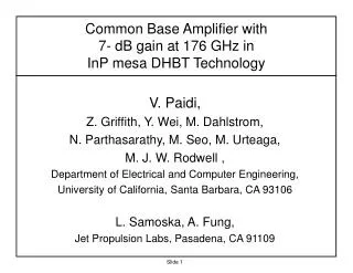
48.8mW Multi-cell InP HBT Amplifier with on-wafer power combining at 220GHz Thomas Reed, Mark Rodwell University of California, Santa Barbara Zach Griffith, Petra Rowell, Miguel Urteaga, Mark Field, Jon Hacker Teledyne Scientific & Imaging, LLC treed@ece.ucsb.edu
220 GHz InP HBT Power Amplifier • mm-Wave Power in Communications and Imaging • 250nm Indium Phosphide HBT Technology • MMIC Power Amplifier Cells & Combiners • Multi-cell Power Amplifier Results Thomas Reed UCSB CSICS M.4
mm-Wave Power in Communications and Imaging Thomas Reed UCSB CSICS M.4
Wiltse, 1997IEEE APS-Symposium, Systems at High Frequency • High Bandwidth Communications • PRec decreases as • High Resolution Imaging Systems • PRec decreases as • Tx/Rx Challenges: • Atmospheric Attenuation • ~2.5 dB/km @ 220 GHz • +3-30dB/km w/ Fog/Rain • High Noise Figure • ~10 dB(InP) sealevel 4 km 220 GHz 9 km Thomas Reed UCSB CSICS M.4
mm-Wave Comm. requires large power • Minimum Received Power • Transmission Losses 300m • Minimum Transmitted Power 29.2 dBm = 0.83 W . . . . . . PA LNA Thomas Reed UCSB CSICS M.4
mm-Wave PA Results Thomas Reed UCSB CSICS M.4
250nm InP HBT Process Thomas Reed UCSB CSICS M.4
Device High Performance Operating Area • Jmax = 12mA/um2 • Vbe,on = 0.85V • VBcbo = 4.5V • Pmax = 15mW/um2 • Vce,hf = 3V high bandwidth Data courtesy Zach Griffith Quiescient Bias Point/ Class A load line Thomas Reed UCSB CSICS M.4
ƒt,ƒmax varies with DC Bias • ft/fmax peak = • 400/700 GHz • ft/fmax = • 350/590 GHz • Highly degraded bandwidth above Vce=3V Thomas Reed UCSB CSICS M.4
Multi-finger HBT Modeling • Device Modeling • Hole in Ground Plane • Multi-finger HBT performance verified • 4-finger HBT • Aemitter= 4x 0.25x6μm2 • ft/fmax = 333/530GHz • 1-finger HBT • ft/fmax = 350/590GHz Base Emitter Collector Ground Plane Another 4-finger cell Thomas Reed UCSB CSICS M.4
Non-Inverted Microstrip Wiring • Local GND • Wider 50Ω than inv. microstrip • Must Model Holes in GND plane • MIM Capacitors, Thin-Film Resistors Metal 4 1µm Metal 3 50 Ω 1µm 5µm • BCB 15µm Metal 2 • (εr = 2.7) BCB MIM CAP Metal 1 • BCB GND Thomas Reed UCSB CSICS M.4
MMIC Power Amplifier Cells & Combiners Thomas Reed UCSB CSICS M.4
MMIC Power Amplifier Cell Design • Cascode Amplifier Topology • Gain, Input/Output Isolation, • Interconnects: ADS Momentum ΔV ΔI High Zo MIM Thomas Reed UCSB CSICS M.4
A 4-finger Amplifier Cell Thomas Reed UCSB CSICS M.4
A 4-finger Amplifier Cell DC Supplies CE CB λ/4 Chokes Thomas Reed UCSB CSICS M.4
A 4-finger Amplifier Cell Input Matching Output Tuning DC Block Bypass Cap Thomas Reed UCSB CSICS M.4
Combining for High MMIC Power • Combine 4:1 and 2:1 for larger total power • Limits to combiners • Large IL at L ≥λg/4 Thomas Reed UCSB CSICS M.4
2:1 Power Combiner Measured 1.25dB insertion loss for Back-to-back Combiners L = λ/4 Cell Combiner √2 * Zo √2 * Zo Zo 2-Cell Power Amplifier with 2:1 power combining. The die is 0.7x0.58 mm2. Thomas Reed UCSB CSICS M.4
4:1 Power Combiner • Reduced to Lumped L/C for design Cell Combiner Measured 1.3 dB Insertion Loss for Back-to-back 4:1 power Combiners. • 4-cell InP HBT amplifier with 4-1 power combiners. The die is 0.7x0.65 mm2. Thomas Reed UCSB CSICS M.4
48.8 mW 4-finger Power Amplifiers Thomas Reed UCSB CSICS M.4
MMIC Measurements and Data • Small Signal Measurement • VNA with 206-340 GHz frequency extender heads • SOLT calibration for circuits • Power Sweep Measurement • 200 & 220 GHz frequency multiplier chains and sub-mm wave power meter • Insertion Loss Calibration VDI Source To Meter Thomas Reed UCSB CSICS M.4
2-Cell PA Results S21=10.9 dB @ 220GHz Pout,max=26.3mW @ 208GHz ΔV = 2, 2.5, 3V Thomas Reed UCSB CSICS M.4
4-Cell PA Results S21 = 10.1 dB @ 220 GHz Pout ≈ 48mW @ 210-220GHz Thomas Reed UCSB CSICS M.4
. 8-Cell Power Amplifiers Pout = 66.1mW @ 215 GHz S21,max = 9.1dB @ 217 GHz 3dB Bandwidth 206-242GHz Measured Pout limited by 220GHz source power Thomas Reed UCSB CSICS M.4
Linear Power Density • InP HBT process is a competitive high power-density technology. Thomas Reed UCSB CSICS M.4
Recapitulation • Modular amplifier cells have been designed to have high gain and high output power. • 4-cell amplifiers show 48.8 mW saturated output power at 220 GHz using InP HBTs. • 8-cell amplifiers show 58 mW output power at 220 GHz but measurements were limited by source power. Thomas Reed UCSB CSICS M.4
THANK YOU! • CSICS Technical Committee • Zach Griffith, Mark Rodwell, and Mark Field • UCSB Rodwell Group Members • DARPA MTO HiFive Program Thomas Reed UCSB CSICS M.4
Questions? Thomas Reed UCSB CSICS M.4
Bonus Slides Thomas Reed UCSB CSICS M.4
mm-Wave Power Amplifiers • Current Power Amplifier Results Key Black – GaN Red – InP HEMT Green – My InP HBT Results Yellow – Other InP HBT Results Thomas Reed UCSB CSICS M.4
Collector Metal Ground Extension DC Blocking Capacitors Ground Plane • Ground Plane hole • Large enough to represent a short at 220GHz. • Blocking Caps create a hole in the ground plane • Inductance (Think Slot Antenna) Port 2 Port 1 DC Block Cap Metal 2 Port 1 Port 2 Metal 2 MIM CAP GND Metal 1 GND Collector Metal Thomas Reed UCSB CSICS M.4
System Components at High Frequency • High Frequency LNAs • 94 GHzInPmHEMT: 3dB NF • (MikkoKarkkainen, et al. Coplanar 94 GHz Metamorphic HEMT Low Noise Amplifiers. CSICS 2006.) • 150-215 GHzInP HBT: 5-12dB NF • (Samoska, L. Towards Terahertz MMIC Amplifiers: Present Status and Trends.MTT-S 2006.) • 300 GHzInP HBT LNA: 11.2dB NF • (J. Hacker, et al. THz MMICs based on InP HBT Technology. IMS 2010.) • 670 GHzInP HEMT: 13dB NF • (Deal, W.R., et al. Low Noise Amplification at 0.67 THz Using 30nm InP HEMTs. Microwave and Wireless Components Letters July 2011.) Thomas Reed UCSB CSICS M.4
Rain, Fog, & Humidy Reduce Range and Reliability rain 50 mm/hr: 20 dB/km, 30-1000 GHz 150 mm/hr : 50 dB/km, 30-1000 GHz Clouds, heavy fog:~(25 dB/km)x(frequency/500 GHz) 90% Humidity: >30 dB/km above 300 GHznondominant below 250 GHz (Rosker 2007 IEEE IMS) Manabe, Yoshida, .1993 EEE Int. Conf. on Communications, tropical deluge heavy rain very heavy fog Liebe, Manabe, Hufford, IEEE Trans Antennas and Propagation, Dec. 1989 rain Olsen, Rogers, Hodge, IEEE Trans Antennas & Propagation Mar 1978 Thomas Reed UCSB CSICS M.4
MMIC Measurements and Data • “Load Pull” Station • Power Sweep using VDI 200 GHz and 220GHz Multiplier Chain • Calorimeter—Erickson sub-mm wave power meter • Calibration • Insertion Loss calibration with the reference plane at the probe tips • Waveguide flange to probe tip insertion loss ~1.7dB VDI Source To Meter Above Photo Courtesy Zach Griffith Thomas Reed UCSB CSICS M.4