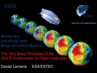
GOCE Technical Presentation
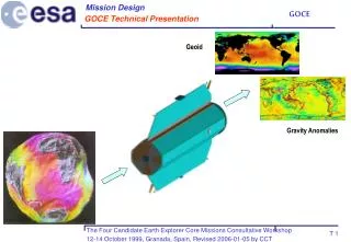
Mission Design. GOCE Technical Presentation. Geoid. Gravity Anomalies. System Concept. Presentation Outline. Mission Rationale Science & Application Mission Design Performance Conclusions. - System Concept - Instruments - Attitude and Drag Control - Conventional Mission Elements

GOCE Technical Presentation
E N D
Presentation Transcript
Mission Design GOCE Technical Presentation Geoid Gravity Anomalies
System Concept Presentation Outline • Mission Rationale • Science & Application • Mission Design • Performance • Conclusions - System Concept - Instruments - Attitude and Drag Control - Conventional Mission Elements - Programmatics
System Concept From Scientific to Satellite Requirements • The scientific requirements are 1 mgal (gravity) and 1 cm (geoid) at 100 km resolution • To carry a gradiometer and a GPS/GLONASS receiver • Using the mission simulation tools, these scientific requirements, have been transformed in mission and satellite requirements: • gravity gradient (mE), • satellite position (cm), • orbit altitude • and mission duration
System Concept Derived Satellite Requirements • Orbit altitude: 250 km • Orbit inclination: 96.5º (Sun-synchronous) • Orbit local time of ascending node: 6:00 • Mission duration: 20 months • Gradiometric performance target: 4 mE/Hz • SST-hl performance target: 2 cm
Mission Design Satellite Configuration • Symmetric • Slender (0.8 m2) • Large Solar Array • Without mechanisms • 770 kg • 1100 W • 4 m long Velocity Zenit Sun
System Concept Mission Timeline
System Concept Observables Frequency Ranges Fy (transversal) • The gravity and the perturbing forces change in space and time • The satellite observe them as time series • Signal and noise are studied in the frequency domain Drag force (mN) Fx (along velocity) s Acceleration PSD (m/(s2sqrtHz)) 7700 km 77 km 770 km Hz
System Concept Instruments Synergy Resolution (km) 200 66.6 2000 10000 Frequency (Hz) • The gradiometer has good performance at high frequency and the SST-hl receiver at low frequency • Overlapping frequency is 0.005 Hz • The gradiometer provides the external accelerations to the SST-hl receiver that provides long term stability to the gradiometer 0.11 0.0038 0.038 0.00038 Gradiometer range (0.005-0.1 Hz) SST-hl receiver range 300
System Concept Satellite Error Budgets Gradient error: SST-hl total error: 2 cm (1 cm, receiver, 1 cm GPS ephemeris, 1 cm satellite accelerations)
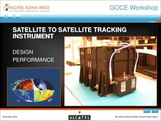
Instruments The Gradiometer • It provides the high resolution terms of the gravity field • Three pairs of accelerometers perpendicular to each other. Baseline 0.5 m • The difference of read-out of a pair of accelerometers provides one component of the gravity gradient • The addition of the read-out provides the external linear acceleration • Angular accelerations are also obtained • Measurement bandwidth (mbw): 0.005-0.1 Hz • Resources: 125 kg, 75 w, 1 Kbps, 0.8 0.8 1.2 m
Instruments The Gradiometer: Accelerometer Principle S C1 C2 S
Instruments The Gradiometer Accelerometer Design and Status • Benefits from many years of development • Pt-Rh proof mass (441 cm, 320 g) grounded by a gold wire. • Control electrodes in gold coated ULE glass. • External body in Invar. • Benefits from many years of development • GOCE drag control allows better accuracy IntegratedView Proof Mass Electrodes Exploded View
Instruments The Gradiometer: Instrument Resolution • 3 mE/Hz specified • The predicted performance curve has been derived from a combination of analysis and test • Predicted results in line with requirements Specified noise value Predicted noise values
ad ac ac ad Instruments The Gradiometer: Instrument Satellite Coupling Errors • External linear and angular accelerations couple with instrument missalignments to produce errors • 1 mE/Hz allocated to this error source. • The resulting gradiometer alignment accuracy is 10-5 rad. It has been verified by test.
Instruments The Gradiometer: Pendulum Test Bench • A servo controlled pendulum test bench has been developed for the testing of the gradiometer • Tilting angles can be controlled down to 10-10 rad • By tilting the platform, alignments and scale factors can be measured to 10 -5 rad
Instruments The Gradiometer: Configuration (Exploded View) Thermally regulated platform External thermal protection Structural support Platform Gradiometer core Mechanical decoupling device Mechanical decoupling device Internal thermal protection Structural support
Instruments The Gradiometer: Configuration (Integrated View)
Instruments The Gradiometer: Thermal Stability • Lack of dimensional stability will produce errors • 0.2 mE/Hz allocated • Two thermal domains configuration • Ultra stable Carbon&Carbon structure • The performances (0.8 mK over 200 s and 9 µK over 10 s) fulfill these requirements
Instruments Calibration Principle ad ac ac ad kd kd • The satellite will be shaken in orbit with specified forces and torques by the micro-thrusters and the accelerometers alignment errors will be measured • This will also be done on ground using the pendulum bench as shaker
Instruments SST-hl GPS/GLONASS Receiver • It provides the low resolution part of the gravity field • 12 channel dual-frequency GPS and GLONASS receiver • Less than 1 cm of measurement noise. Two off-the shelf receivers fulfilling GOCE needs will be available in Europe soon: GRAS and Lagrange • Reference interface data are: • Planar hemispherical zenith looking antenna • System is: 10 kg, 40 w, 2 Kbps. Electronic box is 250 164 203 mm, Antenna is 300 300 50 mm,
Attitude and Drag Control System Requirements • Linear acceleration: 10-6 m/s2 (total), 2.5·10-8 m/s2Hz (mbw) • Angular acceleration: 10-6 rad/s2 (total), 2.5·10-8 rad/s2 Hz (mbw) • Pointing: 0.35 mrad (total), 8.6 ·10-6 rad/ Hz (mbw) • The analysis including close-loop simulation, has demonstrated that the requirements are fulfilled • Low flying altitude drives: redundant system for the ‘nominal’ modes plus fully independent emergency mode sensors and actuators
Attitude and Drag Control Architecture and drag Safe mode Normal mode
Attitude and Drag Control Performance m/s2Hz unit/Hz Drag requirement • Pointing requirement: 8.6·10-6 rad/Hz fulfilled (2 mEHz) • Drag control requirements: 2.5·10-8 m/s2Hz fulfilled (0.9mEHz) Pointing requirement 10-5 10-7 Velocity requirement 10-7 Acceleration requirement 10-8 10-8 10-9 10-3 10-1 10-3 10-1 Frequency (Hz) Frequency (Hz)
Attitude and Drag Control Ion-Thrusters Principles and Requirements • It is used to compensate the atmospheric drag • Xe gas is first ionised, then accelerated by high voltage and expelled. This produces thrust • The main requirements are: • Normal thrust range: 1-12 mN. Orbit change thrust: 20 mN • Minimum thrust step: 18 N • Thrust modulation speed: 10 mN in 1000 s and 25N in 0.1 s • Bandwidth 10 Hz • Two thrusters (full redundancy) located at the bottom of the satellite
Attitude and Drag Control Ion-Thrusters Development Status • Most requirements have been verified by analysis or by test • The verification of the long term thrust direction stability is pending Ion-thruster test set-up 25 N step in 1 ms Thruster step test result
Conventional Mission Elements Thermal and Structural Elements Conventional thermal control Structure allows easy assembly and disassembly Equipment radiator Upper equipment bay Instrument radiators Instrument bay Equipment radiator Lower equipment bay
Conventional Mission Elements Avionics 4 Kbps 1 Mbps S band 1 Gbit memory Data Handling Communications Attitude and Drag Control 24-36 V power bus Solar Array 265 1100 W Ion Propulsion Power control electronics Data bus MIL-1553 SA Battery 265 Wh Thermal Control Data bus Gradiometer Radiation Monitor SST receiver
Conventional Mission Elements Satellite Mass and Power Budget
Conventional Mission Elements GOCE Operations • 5 Kbps, no real time data, instruments always on • Once a month recalibration • Change of altitude several times during the mission • Robust strategy to avoid mission loss in case of failure of the drag or attitude control • Sophisticated attitude and drag control modes • Autonomous and resilient satellite • S band 1 Mbps down-link rate • Two passes per day are enough for data downlink
Conventional Mission Elements Ground Segment Architecture • IGS data for POD • Geoid and gravity fields are produced during the mission and consolidated once the mission is finished • Real time checking of the data quality is done using the trace-less property
Programmatics Development and Mission Risk • The gradiometer benefits from the accelerometers development • The SST-hl receiver is available • The already performed pre-development on the ion-thrusters provide a very high degree of confidence on the approach • The proportional micro-thrusters have not yet gone through all its key development stages but the last developments are encouraging • Launch window is one month. If it is not met it would imply one year launch delay. • Low flying altitude is necessary. Specific features have been implemented to minimize this risk: redundancy, safe mode, aerodynamic stability, autonomy. Up to 20 days without ion-thrusters can be recovered
Programmatics Satellite at ESTEC in 2004
Programmatics GOCE Testing
Schedule 2006 2000 2001 2002 2003 2004 2005 Phase A Phase B ESA Phases C/D Phase E Launch Gravity User Workshops GOCE User Milestones ESRIN Workshop EGS IAG/IAPSO AO Workshop ESTEC Workshop ISSI AO’s Cal/Val AO Data AO EGG-C: Level 1 - Level 2 Data Processing Architecture HPF/CMF&RPF Development National Entities Data Processing ESAG ? Airborne Gravity Survey Validation Campaign?
Programmatics Development and Mission Risk • The gradiometer benefits from the accelerometers development • The SST-hl receiver is available • The already performed pre-development on the ion-thrusters provide a very high degree of confidence on the approach • The proportional micro-thrusters have not yet gone through all its key development stages but the last developments are encouraging • Launch window is one month. If it is not met it would imply one year launch delay. • Low flying altitude is necessary. Specific features have been implemented to minimize this risk: redundancy, safe mode, aerodynamic stability, autonomy. Up to 20 days without ion-thrusters can be recovered