Chapter 5: A Multi-Cycle CPU
200 likes | 336 Views
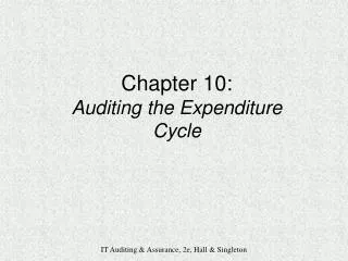
Chapter 5: A Multi-Cycle CPU. The Multi-cycle idea. We can use any logic block once each cycle. PC. Read reg. 1. Read address. Read data 1. Memory. Read reg. 2. Read data. Registers. Result. Write address. Write reg. Read data 2. Write data. Write data. Memory:

Chapter 5: A Multi-Cycle CPU
E N D
Presentation Transcript
Chapter 5: A Multi-Cycle CPU
The Multi-cycle idea... We can use any logic block once each cycle PC Read reg. 1 Read address Read data 1 Memory Read reg. 2 Read data Registers Result Write address Write reg Read data 2 Write data Write data Memory: Holds Instructions Holds Data ALU: Computes R-type value Computes Address Computes next PC Computes Branch Registers: Hold data values
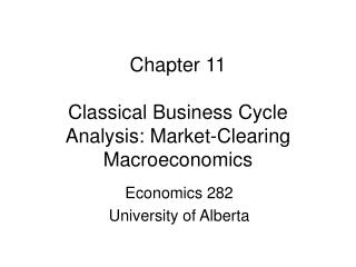
Registers PC 0 0 Read reg num A Read address Read reg data A 1 1 Memory Read reg num B Zero Read data Result Write address 0 Write reg num 0 Read reg data B 1 Write data 1 Write reg data 2 1 3 0 Sh.Left2 signextend Multi-cycle Datapath Update PC=PC+4 Load Instruction:Need address Read Instructionfrom memory Decode,Readregisters (R-type) Start: PC Do ALU Op PC [25-21] [20-16] [15-11] 4 WriteResult reg. Branch 16 32 [15-0] Write result Store Instr. Read from Memory
Breaking instructions into cycles Mem ALU Note: Some of theseare unneeded, butthey don’t hurt! Instruction Fetch, Increment PC Decode Instruction, Access Registers Jump Reg Update PC Compute Branch Target ALU LW,SW ALU Branch R-type Compute Memory Address ALU If condition holdsupdate PC to Target Execute Instruction ALU Mem Read/Write Memory Write Register Reg Can use each major block (ALU,reg,mem)once each cycle Reg Write Register LW
Registers PC 0 0 Read reg num A Address Read reg data A 1 1 Memory Read reg num B Zero Read data Result 0 Write reg num 0 Read reg data B 1 Write data 1 Write reg data 2 1 3 0 Sh.Left2 signextend ALUcontrol Note: The control signals will be constant during each cycle, but may change during the multi-cycle instruction Multi-cycle Control Control ALUOp Inst[31-26] IorD ALUSelB MemRead ALUSelA MemWrite MemToReg RegWrite RegDest PC [25-21] [20-16] [15-11] 4 16 32 [15-0] [5-0]
Registers PC 0 0 Read reg num A Address Read reg data A 1 1 Memory Read reg num B Zero Read data Result 0 Write reg num 0 Read reg data B 1 Write data 1 Write reg data 2 1 ALUcontrol 3 0 Sh.Left2 signextend Instr. [31-0] Instr. Reg 1. Memory reads overwrite the instruction - Add Instr. Reg. Issues - Add PCWrite Signal 2. ALU overwrites PC every cycle Add PCWriteCond Signal PCWrite 3. Branches? Control PCWriteCond ALUOp Zero Inst[31-26] IorD ALUSelB MemRead ALUSelA MemWrite MemToReg RegWrite IRWrite RegDest PC [25-21] [20-16] [15-11] 4 16 32 [15-0] [5-0]
Sh.Left2 2 0 1 Registers PC 0 0 Read reg num A Address Read reg data A 1 1 Memory Read reg num B Zero Read data Result 0 Write reg num 0 Read reg data B 1 Write data 1 Write reg data 2 1 ALUcontrol 3 0 Sh.Left2 signextend Instr. [31-0] Instr. Reg On branches, the PC is alwayswritten with Zero! Issues PCSource 28 26 Concat. 32 PCWrite Control 4 PCWriteCond ALUOp Zero Inst[31-26] Inst[25-0] [31-28] IorD MemRead Logic for Jumps ALUSelA MemWrite MemToReg RegWrite IRWrite RegDest PCorPC+4 [25-21] A [20-16] ALUOut ALUSelB [15-11] B 4 MDR ALU Out: Save result of ALU for use on next cycle MDR: Save result of read for use on next cycle A, B: Save registers for use on next cycle 16 32 [15-0] [5-0]
Sh.Left2 2 0 1 Registers PC 0 0 Read reg num A Address Read reg data A 1 1 Memory Read reg num B Zero Read data Result 0 Write reg num 0 Read reg data B 1 Write data 1 Write reg data 2 1 ALUcontrol 3 0 Sh.Left2 signextend Instr. [31-0] Instr. Reg Cycle 1 All instructions Instruction Fetch PCSource 28 26 Concat. 32 0 1 x PCWrite Control 4 PCWriteCond 0 ALUOp Zero Inst[25-0] [31-28] Inst[31-26] 0 IorD MemRead 1 1 x 0 x 0 ALUSelA MemWrite MemToReg RegWrite IRWrite RegDest PCorPC+4 0 [25-21] A [20-16] ALUOut ALUSelB 1 [15-11] B 4 IorD=0MemRead=1MemWrite=0IRWrite=1ALUSelA=0 ALUSelB=1 MDR ALUOp=00PCWrite=1PCSource=0RegWrite=0 16 32 [15-0] [5-0]
Cycle 2 All instructions Sh.Left2 2 0 1 Registers PC 0 0 Read reg num A Address Read reg data A 1 1 Memory Read reg num B Zero Read data Result 0 Write reg num 0 Read reg data B 1 Write data 1 Write reg data 2 1 ALUcontrol 3 0 Sh.Left2 signextend Instr. [31-0] Instr. Reg Instr. Decode/Reg. Fetch PCSource 28 26 Concat. 32 x 0 0 PCWrite Control 4 PCWriteCond 0 ALUOp Zero Inst[25-0] [31-28] Inst[31-26] 0 x IorD MemRead x 0 0 x 0 ALUSelA MemWrite MemToReg RegWrite IRWrite RegDest PCorPC+4 0 [25-21] A [20-16] ALUOut ALUSelB 3 [15-11] B 4 MDR MemRead=0MemWrite=0IRWrite=0ALUSelA=0 ALUSelB=3 ALUOp=00PCWrite=0PCWriteCond=0RegWrite=0 16 32 [15-0] [5-0]
Sh.Left2 2 0 1 Registers PC 0 0 Read reg num A Address Read reg data A 1 1 Memory Read reg num B Zero Read data Result 0 Write reg num 0 Read reg data B 1 Write data 1 Write reg data 2 1 ALUcontrol 3 0 Sh.Left2 signextend Instr. [31-0] Instr. Reg Cycle 3 R-Type x R-type Execution PCSource 28 26 Concat. 32 0 PCWrite 0 Control 4 PCWriteCond 2 ALUOp Zero Inst[25-0] [31-28] Inst[31-26] x IorD MemRead x 0 0 x 0 0 ALUSelA MemWrite MemToReg RegWrite IRWrite RegDest PCorPC+4 1 [25-21] A [20-16] ALUOut ALUSelB 0 [15-11] B 4 MemRead=0MemWrite=0IRWrite=0ALUSelA=1 ALUSelB=0 MDR ALUOp=10PCWrite=0PCWriteCond=0RegWrite=0 16 32 [15-0] [5-0]
Sh.Left2 2 0 1 Registers PC 0 0 Read reg num A Address Read reg data A 1 1 Memory Read reg num B Zero Read data Result 0 Write reg num 0 Read reg data B 1 Write data 1 Write reg data 2 1 ALUcontrol 3 0 Sh.Left2 signextend Instr. [31-0] Instr. Reg Cycle 4 R-Type R-type Completion x PCSource 28 26 Concat. 32 0 0 PCWrite Control 4 PCWriteCond x ALUOp Zero Inst[25-0] [31-28] Inst[31-26] x IorD MemRead 0 1 1 0 x 0 ALUSelA MemWrite MemToReg RegWrite IRWrite RegDest PCorPC+4 x [25-21] A [20-16] ALUOut ALUSelB x [15-11] B 4 MemRead=0MemWrite=0 RegDest=1 MDR PCWrite=0PCWriteCond=0RegWrite=1MemToReg=0 16 32 [15-0] [5-0]
Sh.Left2 2 0 1 Registers PC 0 0 Read reg num A Address Read reg data A 1 1 Memory Read reg num B Zero Read data Result 0 Write reg num 0 Read reg data B 1 Write data 1 Write reg data 2 1 ALUcontrol 3 0 Sh.Left2 signextend Instr. [31-0] Instr. Reg Cycle 3 BEQ Branch if Equal 1 PCSource 28 26 Concat. 32 0 PCWrite 1 Control 4 PCWriteCond 1 ALUOp Zero Inst[25-0] [31-28] Inst[31-26] x IorD MemRead x x 0 x 0 0 ALUSelA MemWrite MemToReg RegWrite IRWrite RegDest PCorPC+4 1 [25-21] A [20-16] ALUOut ALUSelB 0 [15-11] B 4 MemRead=0MemWrite=0ALUSelA=1 ALUSelB=0PCSource=1 MDR ALUOp=01PCWrite=0PCWriteCond=1RegWrite=0 16 32 [15-0] [5-0]
Sh.Left2 2 0 1 Registers PC 0 0 Read reg num A Address Read reg data A 1 1 Memory Read reg num B Zero Read data Result 0 Write reg num 0 Read reg data B 1 Write data 1 Write reg data 2 1 ALUcontrol 3 0 Sh.Left2 signextend Instr. [31-0] Instr. Reg Cycle 3 Jump Jump PCSource 28 26 Concat. 2 32 1 PCWrite Control 4 PCWriteCond x x ALUOp Zero Inst[25-0] [31-28] Inst[31-26] x IorD MemRead x 0 x 0 x 0 ALUSelA MemWrite MemToReg RegWrite IRWrite RegDest x PCorPC+4 [25-21] A [20-16] ALUOut ALUSelB x [15-11] B 4 MDR MemRead=0MemWrite=0 PCWrite=1RegWrite=0PCSource=2 16 32 [15-0] [5-0]
Cycle 3 LW,SW Sh.Left2 2 0 1 Registers PC 0 0 Read reg num A Address Read reg data A 1 1 Memory Read reg num B Zero Read data Result 0 Write reg num 0 Read reg data B 1 Write data 1 Write reg data 2 1 ALUcontrol 3 0 Sh.Left2 signextend Instr. [31-0] Instr. Reg x Memory Addr. Completion PCSource 28 26 Concat. 32 0 0 PCWrite Control 4 PCWriteCond 0 ALUOp Zero Inst[25-0] [31-28] Inst[31-26] x IorD MemRead 0 x 0 x 0 0 ALUSelA MemWrite MemToReg RegWrite IRWrite RegDest 1 PCorPC+4 [25-21] A [20-16] ALUOut ALUSelB 2 [15-11] B 4 MemRead=0MemWrite=0IRWrite=0ALUSelA=1 ALUSelB=2 MDR ALUOp=00PCWrite=0PCWriteCond=0RegWrite=0 16 32 [15-0] [5-0]
Sh.Left2 2 0 1 Registers PC 0 0 Read reg num A Address Read reg data A 1 1 Memory Read reg num B Zero Read data Result 0 Write reg num 0 Read reg data B 1 Write data 1 Write reg data 2 1 ALUcontrol 3 0 Sh.Left2 signextend Instr. [31-0] Instr. Reg Cycle 4 LW Memory Read PCSource 28 26 Concat. x 32 0 0 PCWrite Control 4 PCWriteCond x ALUOp Zero 1 Inst[25-0] [31-28] Inst[31-26] IorD MemRead x 0 1 x 0 0 ALUSelA MemWrite MemToReg RegWrite IRWrite RegDest x PCorPC+4 [25-21] A [20-16] ALUOut ALUSelB x [15-11] B 4 MDR MemRead=1MemWrite=0IRWrite=0 PCWrite=0PCWriteCond=0RegWrite=0 IorD=1 16 32 [15-0] [5-0]
Sh.Left2 2 0 1 Registers PC 0 0 Read reg num A Address Read reg data A 1 1 Memory Read reg num B Zero Read data Result 0 Write reg num 0 Read reg data B 1 Write data 1 Write reg data 2 1 ALUcontrol 3 0 Sh.Left2 signextend Instr. [31-0] Instr. Reg Cycle 5 LW ReadWriteBack x PCSource 28 26 Concat. 32 0 0 PCWrite Control 4 PCWriteCond x ALUOp Zero x Inst[25-0] [31-28] Inst[31-26] IorD MemRead x 1 0 1 0 0 ALUSelA MemWrite MemToReg RegWrite IRWrite RegDest x PCorPC+4 [25-21] A [20-16] ALUOut ALUSelB x [15-11] B 4 MemRead=0MemWrite=0RegDest=0 MemtoReg=1 MDR PCWrite=0PCWriteCond=0RegWrite=1MemToReg=1 16 32 [15-0] [5-0]
Sh.Left2 2 0 1 Registers PC 0 0 Read reg num A Address Read reg data A 1 1 Memory Read reg num B Zero Read data Result 0 Write reg num 0 Read reg data B 1 Write data 1 Write reg data 2 1 ALUcontrol 3 0 Sh.Left2 signextend Instr. [31-0] Instr. Reg Cycle 4 SW Memory Write x PCSource 28 26 Concat. 32 0 0 PCWrite Control 4 PCWriteCond x ALUOp Zero x Inst[25-0] [31-28] Inst[31-26] IorD MemRead x x 0 x 0 1 ALUSelA MemWrite MemToReg RegWrite IRWrite RegDest x PCorPC+4 [25-21] A [20-16] ALUOut ALUSelB x [15-11] B 4 MemRead=0MemWrite=1 MDR PCWrite=0PCWriteCond=0RegWrite=0 16 32 [15-0] [5-0]
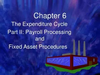
Control Finite State Machine ALUSelA=0 ALUSelB=11ALUOp=0 Instr. Decode/Register Fetch IorD=0MemRead=1IRWrite=1ALUSelA=0 ALUSelB=1ALUOp=00PCWrite=1PCSource=00 t1 Instr. Fetch t0 LW or SW Jump t2 BEQ Jump ALUSelA=1 ALUSelB=2ALUOp=0 Branch Execution t8 t9 Mem. Addr.Completion R-type ALUSelA=1 ALUSelB=0PCSource=1ALUOp=1PCWriteCond=1 ALUSelA=1 ALUSelB=0ALUOp=2 PCWrite=1PCSource=10 t6 t3 MemRead=1IorD=1 LW Memory Access SW t7 t4 RegDest=1RegWrite=1MemToReg=0 t5 MemWrite=1 IorD=1 RegDest=0RegWrite=1MemToReg=1 Memory Access R-typeCompletion Write-back
Implementing the Control • Implementing a Finite State Machine is straightforward • 10 states --> 4 flipflops • Choose binary representations for each state • Create state transition table • Map to flipflop type • Using K-maps, build a function for each control output • 50-70 Gates • Or..., Put the FSM into a computer program and trust it
Evaluation • Reuse common parts • Only one ALU in the design, but more complexity • Multi-cycle goals: • Merge the memories • Success! • Get rid of worst-case cycle time constraint • R-type: 4 cycles, Branch: 3 cycles, Jump: 3 cycles, LW: 5 cycles, SW: 4 cycles • Will cycle time be 1/5 that of single cycle? • No, more like 1/3 or 1/4 of the cycle time • We still will win in most cases