Chapter 2 Assemblers intel/multi-core/demos.htm
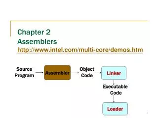
Chapter 2 Assemblers http://www.intel.com/multi-core/demos.htm. Assembler. Linker. Source Program. Object Code. Executable Code. Loader. Outline. 2.1 Basic Assembler Functions A simple SIC assembler Assembler tables and logic 2.2 Machine-Dependent Assembler Features

Chapter 2 Assemblers intel/multi-core/demos.htm
E N D
Presentation Transcript
Chapter 2Assemblershttp://www.intel.com/multi-core/demos.htm Assembler Linker Source Program Object Code Executable Code Loader
Outline • 2.1 Basic Assembler Functions • A simple SIC assembler • Assembler tables and logic • 2.2 Machine-Dependent Assembler Features • Instruction formats and addressing modes • Program relocation • 2.3 Machine-Independent Assembler Features • 2.4 Assembler Design Options • Two-pass • One-pass • Multi-pass
2.1 Basic Assembler Functions • Figure 2.1 shows an assembler language program for SIC. • The line numbers are for reference only. • Indexing addressing is indicated by adding the modifier “,X” • Lines beginning with “.” contain comments only. • Reads records from input device (code F1) • Copies them to output device (code 05) • At the end of the file, writes EOF on the output device, then RSUB to the operating system
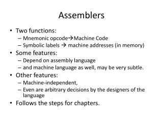
2.1 Basic Assembler Functions • Assembler directives (pseudo-instructions) • START, END, BYTE, WORD, RESB, RESW. • These statements are not translated into machine instructions. • Instead, they provide instructions to the assembler itself.
2.1 Basic Assembler Functions • Data transfer (RD, WD) • A buffer is used to store record • Buffering is necessary for different I/O rates • The end of each record is marked with a null character (0016) • Buffer length is 4096 Bytes • The end of the file is indicated by a zero-length record • When the end of file is detected, the program writes EOF on the output device and terminates by RSUB. • Subroutines (JSUB, RSUB) • RDREC, WRREC • Save link (L) register first before nested jump
2.1.1 A simple SIC Assembler • Figure 2.2 shows the generated object code for each statement. • Loc gives the machine address in Hex. • Assume the program starting at address 1000. • Translation functions • Translate STL to 14. • Translate RETADR to 1033. • Build the machine instructions in the proper format (,X). • Translate EOF to 454F46. • Write the object program and assembly listing.
2.1.1 A simple SIC Assembler • A forward reference • 10 1000 FIRST STL RETADR 141033 • A reference to a label (RETADR) that is defined later in the program • Most assemblers make two passes over the source program • Most assemblers make two passes over source program. • Pass 1 scans the source for label definitions and assigns address (Loc). • Pass 2 performs most of the actual translation.
2.1.1 A simple SIC Assembler • Forward reference • Reference to a label that is defined later in the program. LocLabelOP CodeOperand 1000 FIRST STL RETADR 1003 CLOOP JSUB RDREC … … … … 1012 J CLOOP … … … … 1033 RETADR RESW 1
2.1.1 A simple SIC Assembler • Example of Instruction Assemble • Forward reference • STCH BUFFER, X 549039 (54)16 1 (001)2 (039)16
2.1.1 A simple SIC Assembler • The object program (OP) will be loaded into memory for execution. • Three types of records • Header: program name, starting address, length. • Text: starting address, length, object code. • End: address of first executable instruction.
2.1.1 A simple SIC Assembler • The symbol ^ is used to separate fields. • Figure 2.3 1E(H)=30(D)=16(D)+14(D)
2.1.1 A simple SIC Assembler • Assembler’s Functions • Convert mnemonic operation codes to their machine language equivalents • STL to 14 • Convert symbolic operands (referred label)to their equivalent machine addresses • RETADR to 1033 • Build the machine instructions in the proper format • Convert the data constants to internal machine representations • Write the object program and the assembly listing
2.1.1 A simple SIC Assembler • The functions of the two passes assembler. • Pass 1 (define symbol) • Assign addresses to all statements (generate LOC). • Check the correctness of Instruction (check with OP table). • Save the values (address) assigned to all labels into SYMBOL table for Pass 2. • Perform some processing of assembler directives. LOC 累加 • Pass 2 • Assemble instructions (op code from OP table, address from SYMBOL table). • Generate data values defined by BYTE, WORD. • Perform processing of assembler directives not done during Pass 1. • Write the OP (Fig. 2.3) and the assembly listing (Fig. 2.2).
2.1.2 Assembler Tables and Logic • Our simple assembler uses two internal tables: The OPTAB and SYMTAB. • OPTAB is used to look up mnemonic operation codes and translate them to their machine language equivalents. • LDA→00, STL→14, … • SYMTAB is used to store values (addresses) assigned to labels. • COPY→1000, FIRST→1000 … • Location Counter LOCCTR • LOCCTR is a variable for assignment addresses. • LOCCTR is initialized to address specified in START. • When reach a label, the current value of LOCCTR gives the address to be associated with that label.
2.1.2 Assembler Tables and Logic • The Operation Code Table (OPTAB) • Contain the mnemonic operation & its machine language equivalents (at least). • Contain instruction format & length. • Pass 1, OPTAB is used to look up and validate operation codes. • Pass 2, OPTAB is used to translate the operation codes to machine language. • In SIC/XE, assembler search OPTAB in Pass 1 to find the instruction length for incrementing LOCCTR. • Organize as a hash table (static table).
2.1.2 Assembler Tables and Logic • The Symbol Table (SYMTAB) • Include the name and value (address) for each label. • Include flags to indicate error conditions • Contain type, length. • Pass 1, labels are entered into SYMTAB, along with assigned addresses (from LOCCTR). • Pass 2, symbols used as operands are look up in SYMTAB to obtain the addresses. • Organize as a hash table (static table). • The entries are rarely deleted from table. COPY 1000 FIRST 1000 CLOOP 1003 ENDFIL 1015 EOF 1024 THREE 102D ZERO 1030 RETADR 1033 LENGTH 1036 BUFFER 1039 RDREC 2039
2.1.2 Assembler Tables and Logic • Pass 1 usually writes an intermediate file. • Contain source statement together with its assigned address, error indicators. • This file is used as input to Pass 2. • Figure 2.4 shows the two passes of assembler. • Format with fields LABEL, OPCODE, and OPERAND. • Denote numeric value with the prefix #. #[OPERAND]
2.2 Machine-Dependent Assembler Features • Indirect addressing • Adding the prefix @ to operand (line 70). • Immediate operands • Adding the prefix # to operand (lines 12, 25, 55, 133). • Base relative addressing • Assembler directive BASE (lines 12 and 13). • Extended format • Adding the prefix + to OP code (lines 15, 35, 65). • The use of register-register instructions. • Faster and don’t require another memory reference.
2.2 Machine-Dependent AssemblerFeatures • SIC/XE • PC-relative/Base-relative addressing op m • Indirect addressing op @m • Immediate addressing op #c • Extended format +op m • Index addressing op m, X • register-to-register instructions COMPR • larger memory → multi-programming (program allocation)
2.2 Machine-Dependent AssemblerFeatures • Register translation • register name (A, X, L, B, S, T, F, PC, SW) and their values (0, 1, 2, 3, 4, 5, 6, 8, 9) • preloaded in SYMTAB • Address translation • Most register-memory instructions use program counter relative or base relative addressing • Format 3: 12-bit disp (address) field • PC-relative: -2048~2047 • Base-relative: 0~4095 • Format 4: 20-bit address field (absolute addressing)
2.2.1 Instruction Formats & Addressing Modes • The START statement • Specifies a beginning address of 0. • Register-register instructions • CLEAR & TIXR, COMPR • Register-memory instructions are using • Program-counter (PC) relative addressing • The program counter is advanced after each instruction is fetched and before it is executed. • PC will contain the address of the next instruction. 10 0000 FIRST STL RETADR 17202D TA - (PC) = disp = 30H – 3H= 2D
140030 • 17202D • 0001 011100100000 0010 1101 • 0001 0100 (14H) 0006 - 001A = disp = -14 (H) • Find 14H 的2’complement • 014= 0000 0001 0100 • = 1111 1110 1011 • + 1 • = 1111 1110 1100 • = F E C
+OP, e=1 Extended n=1, i=1, OPcode+3, Simple @m, n=1, i=0, OPcode+2, Indirect #C, n=0, i=1, OPcode+1, Immediate xbpe 2: PC-relative 4: base-relative 8: index (OP m,X) 1: extended 1100 = C
2.2.1 Instruction Formats & Addressing Modes 40 0017 J CLOOP 3F2FEC 0006 - 001A = disp = -14 (H) • Base (B), LDB #LENGTH, BASE LENGTH 160 104E STCH BUFFER, X 57C003 TA-(B) = 0036 - (B) = disp = 0036-0033 = 0003 • Extended instruction 15 0006 CLOOP +JSUB RDREC 4B101036 • Immediate instruction 55 0020 LDA #3 010003 133 103C +LDT #4096 75101000 • PC relative + indirect addressing (line 70)
2.2.2 Program Relocation • Absolute program, relocatable program
2.2.2 Program Relocation • Modification record (direct addressing) • 1 M • 2-7 Starting location of the address field to be modified, relative to the beginning of the program. • 8-9 Length of the address field to be modified, in half bytes. M^000007^05
2.3 Machine-Independent Assembler Features • Write the value of a constant operand as a part of the instruction that uses it (Fig. 2.9). • A literal is identified with the prefix = 45 001A ENDFIL LDA =C’EOF’ 032010 • Specifies a 3-byte operand whose value is the character string EOF. 215 1062 WLOOP TD =X’05’ E32011 • Specifies a 1-byte literal with the hexadecimal value 05
2.3.1 Literals • Literal pools • Assembler directive LTORG, it creates a literal pool that contains all of the literal operands used since the previous LTORG. • At the end of the program (Fig. 2.10). • The difference between literal operands and immediate operands (=, #) • Immediate addressing, the operand value is assembled as part of the machine instruction, no memory reference. • With a literal, the assembler generates the specified value as a constant at some other memory location. The address of this generated constant is used as the TA for the machine instruction, using PC-relative or base-relative addressing with memory reference.