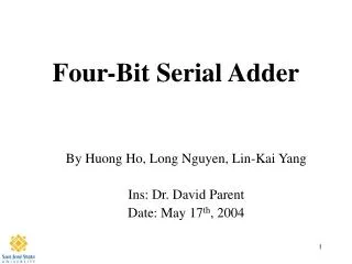
Serial Two’s Complement
Serial Two’s Complement. Review FSM and controller Serial two’s complement sequential circuit Register Transfer Language RTL Description A design with structural description A design with two processes Read On 2’s complement from Digital Design text

Serial Two’s Complement
E N D
Presentation Transcript
Serial Two’s Complement • Review FSM and controller • Serial two’s complement sequential circuit • Register Transfer Language RTL Description • A design with structural description • A design with two processes • Read • On 2’s complement from Digital Design text • Bhasker Ch. 6 pp 125-137 (structural description)
FSM Input Logic Output Present state Next state ck Storage
Two’s Complement Sequential Circuit 2’s Complement Procedures • One’s complement and add one • This is the same as • Copy all the consecutive 0’s from right to left up to (including) the first ‘1’, then one’s complement the remaining bits • E.g., 2’sC of 1011_0100 is • Copy consecutive zero’s from right to left and the first one … 100 Then complement the rest 0100_ 1100
Block Diagram • The output y is the 2’s complement of the input string x after reset Input x(t) x: 0 1 0 1 0 1 0 0 t: 7 6 5 4 3 2 1 0 t=clock cycles Output y(t) y: 1 0 1 0 1 1 0 0 t: 7 6 5 4 3 2 1 0 t=clock cycles Twos_C Ck Reset Entity twos_c is Port(x,ck,reset : in std_logic; z : out std_logic); End twos_c;
Architecture beh of twos_c is Type state_type is (init, complement); Signal n_s : state_type; Begin p1: process(ck) begin if ck='1' and ck'event then if reset = '1' then n_s <= init; elsif reset = '0' then case n_s is when init => z <= x; if x = '0' then n_s <= init; elsif x = '1' then n_s <= complement; end if; when complement => z <= not x; end case; end if; end if; end process p1; end beh;
Design with structural description X: in std_logic_vector(n-1 downto 0) Twos_C z w Shift Reg Serial_in_R en sel Ck Reset controller Go RS Y: out std_logic_vector(n-1 downto 0)
Declare Components Architecture struc of twos_c_system is Component shift_reg Generic(n : natural := 4) Port(x: in std_logic_vector(n-1downto 0); sel: in sh_reg_sel_type; ck: std_logic; z: out std_logic); End component; Component twos_c Port(x,ck,reset: in std_logic; z: out std_logic); End component; Component controller … End component;
Declare Internal Signal Wires Signal reset,z,w: std_logic; Signal sel: sh_reg_sel_type; Instantiate Components Begin –- architecture body In_reg: Shift_reg: generic map(n)port map(x,sel,ck,z); out_reg:serial_in_r: generic map(n) port map(w,en,ck,y); Core: Twos_c port map(z,ck,reset,w); Fsm: controller port map(…
Behavioral description with two processes • Declare signals for registers • Declare signals for controls • Process P1 (state machine) computes the two’s complement • Process P2 (state machine) handles input/output and controls • Interprocesses communication using signal • Hierarchical state machine
Design with two processes X: std_logic_vector(7 downto 0) P1 Reg_x Reg_z shift Load/shift Ck P1_reset P2 Go reset Z:std_logic_vector(7 downto 0)
entity serial2sc is port ( x : in std_logic_vector(7 downto 0); ck ,go, reset : in std_logic; z : out std_logic_vector(7 downto 0)); end serial2sc; architecture beh of serial2sc is type p1_states is (init, complement); signal p1_n_s : p1_states; type p2_states is (idle, debounce, load, compute); signal p2_n_s : p2_states; subtype my_integer is integer range 0 to 7; signal count: my_integer; signal p1_reset, z_bit : std_logic; signal : reg_x, reg_z: std_logic_vector(7 downto 0); begin
p1: process(ck) begin if ck='1' and p1_reset = '1' then p1_n_s <= init; elsif ck='1' and p1_reset = '0' then case p1_n_s is when init => z_bit <= reg_x(0); if reg_x(0)='0' then p1_n_s <= init; elsif reg_x(0)='1' then p1_n_s <= complement; end if; when complement => z_bit <= not reg_x(0); end case; end if; end process p1;
p2: process(ck) begin if ck='1' and reset = '1' then p2_n_s <= idle; elsif ck='1' and reset = '0' then case p2_n_s is when idle => if go = '1' then p2_n_s <= debounce; elsif go = '0' the p2_n_s <= idle; end if; when debounce => if go = '1' then p2_n_s <= debounce; elsif go = '0' the p2_n_s <= load; end if;
when load => reg_x <= x; p1_reset <= '1'; count <= 0; p2_n_s <= compute; when compute p1_reset <= '0'; reg_x <= '0'®_x(7 downto (count+1)); reg_z <= z_bit®_z(7 downto 1); if count = 7 then p2_n_s <= idle; elsif count < 7 then p2_n_s <= compute; end if; count <= count + 1; end case; end if; end process p2; end beh;