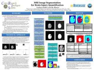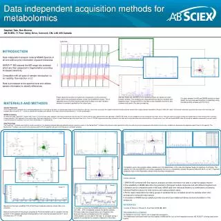
MRI Acquisition Methods for Brain Morphometry
MRI Acquisition Methods for Brain Morphometry. Andr é J. W. van der Kouwe Athinoula A. Martinos Center, Massachusetts General Hospital. Avoiding Imaging Artifacts.

MRI Acquisition Methods for Brain Morphometry
E N D
Presentation Transcript
MRI Acquisition Methods for Brain Morphometry André J. W. van der Kouwe Athinoula A. Martinos Center, Massachusetts General Hospital
Avoiding Imaging Artifacts Small mistakes in the choice of imaging protocol at the beginning of a study can result in a large amount of manual intervention work later on.
Examples of Artifacts Chemical shift artifact
Examples of Artifacts Motion artifact INTRuST (Posttraumatic Stress Disorder and Traumatic Brain Injury Clinical Consortium) NLC (Neuroimaging Leadership Core): Shenton, Kikinis, Rosen (PIs), Helmer, van der Kouwe, Kubicki, Pasternak (http://intrust.spl.harvard.edu)
Examples of Artifacts Intrinsic susceptibility artifact (EPI images)
Examples of Artifacts Susceptibility artifact from metal INTRuST (Posttraumatic Stress Disorder and Traumatic Brain Injury Clinical Consortium) NLC (Neuroimaging Leadership Core): Shenton, Kikinis, Rosen (PIs), Helmer, van der Kouwe, Kubicki, Pasternak (http://intrust.spl.harvard.edu)
Examples of Artifacts Wrap in phase encoding direction (3D has two PE directions) INTRuST (Posttraumatic Stress Disorder and Traumatic Brain Injury Clinical Consortium) NLC (Neuroimaging Leadership Core): Shenton, Kikinis, Rosen (PIs), Helmer, van der Kouwe, Kubicki, Pasternak (http://intrust.spl.harvard.edu)
Examples of Artifacts Dura adjacent to cortex
Examples of Artifacts Poor contrast
MRI Acquisition Methods for Brain Morphometry 1. Contrasts: Bandwidth matched morphometry (PD, T1, T2 and T2*) 2. Artifacts: Distortions (B0 and gradient distortions) 3. Positioning: AutoAlign and motion correction
Contrasts: Bandwidth matched morphometry(PD, T1, T2 and T2*)Artifacts: Distortions(B0 and gradient distortions)
Contrasts: PD, T1, T2 and T2* weighting Which is best for brain morphometry/FreeSurfer? PD-weighting (proton/spin density) + T1-weighting (gray/white contrast) + T2-weighting (bright CSF/tumor) FLASH 5° FLASH 30° T2-SPACE
Contrasts: PD, T1, T2 and T2* weighting T2*-weighting (bone/dark blood/blood oxygenation/susceptibility) Bone Anatomical fMRI/BOLD Susceptibility Radial UTE FLASH EPI SWI (FLASH) 70 µs 2 - 10 ms 20 - 40 ms 30 ms TE
Contrasts: PD, T1, T2 and T2* weighting Which is best for brain morphometry/FreeSurfer? FLASH 30° MPRAGE MPRAGE (FLASH with inversion) has the best contrast for FreeSurfer because: • MPRAGE parameters chosen for “optimal” gray/white/CSF contrast • FreeSurfer statistics (priors) based on MPRAGE
Recommended protocol: bandwidth matched On the Martinos Center scanners under MGH → Morphometry: Localizer 0:13 AAScout 0:46 For cortical thickness (MEMPRAGE): tfl_mgh_me_4echoes_iPAT2 1 x 1 x 1 mm3 6:03 For segmentation and PD/T1 estimation (MEFLASH): gre_mgh_me_5deg_iPAT2 1 x 1 x 1 mm3 8:28 gre_mgh_me_30deg_iPAT2 1 x 1 x 1 mm3 8:28 For T2 contrast (lesion detection): T2_SPACE_iPAT2 1 x 1 x 1 mm3 4:43 Bandwidths are matched and iPAT/multichannel coils reduce time Detailed recommended protocols at http://www.nmr.mgh.harvard.edu/~andre Fischl, MGH
Why multi-echo bandwidth matched? Geometric distortion with gradient echo sequences is proportional to ∆B0, inversely proportional to bandwidth and follows readout direction MPRAGE with positive readout direction, BW 195 Hz/px (1 pixel shift for each 195 Hz error in B0)
Why multi-echo bandwidth matched? Geometric distortion with gradient echo sequences is proportional to ∆B0, inversely proportional to bandwidth and follows readout direction MPRAGE with negative readout direction, BW 195 Hz/px (-1 pixel shift for each 195 Hz error in B0)
Why multi-echo bandwidth matched? High bandwidth results in: • smaller B0 (susceptibility) related geometric distortions • but lower SNR With multiecho sequences: • individual echoes have high bandwidth/low SNR • but echoes are combined to recover SNR with low distortion MEMPRAGE, MEFLASH and T2-SPACE can be bandwidth-matched: • edges of structures align across contrasts
What areas of the cortical surface do B0 distortions affect the most? Distances between surfaces measured with opposite readout directions (since both surfaces move, cortical thickness changes are much smaller) MPRAGE (+) vs MPRAGE (-) MEMPRAGE (+-+-) vs MEMPRAGE (-+-+) Benner, Salat, MGH
Why collect FLASH at different flip angles? FLASH (spoiled gradient echo) sequence is versatile, simple and easily modeled: Effective T1 and PD (in arbitrary units) can be estimated at each voxel from two FLASH scans with differing flip angles using the FLASH steady-state equation (assume TE << T2*) T2* can be estimated at each voxel from the signal decay across eight echoes of the multiecho FLASH scan (MEF) The T1 and PD volumes can be used to synthesize a volume at any flip angle Fischl, MGH; Dale, UCSD
T1 / PD / T2* fitting with FreeSurfer FreeSurfer command to fit T1, PD and T2* from FLASH volumes: mri_ms_fitparms [options] [vol_1] [vol_2] ... [output_dir] For example: mri_ms_fitparms -tr 20 -te 6 -fa 5 flash5.mgh -tr 20 -te 6 -fa 30 flash30.mgh parameter_maps (parameters_maps/ is destination directory) FreeSurfer command to synthesize volume from T1 and PD: mri_synthesize [options] <TR> <alpha> <TE> <T1 vol> <PD vol> <output> For example: mri_synthesize 20 23 0 T1.mgz T2.mgz synth_23.mgz Fischl, MGH; Dale, UCSD
Why collect FLASH at different flip angles? Volumes with arbitrary flip angles can be synthesized from PD and T1 50° 0° PD volume T1 volume Synthetic volume Ernst angle (flip angle α at which signal is maximized) can be calculated from T1 of tissue (cos α = e-TR/T1) but this is not necessarily the angle of maximum contrast Meintjes, UCT; Jacobson, WSU
Why collect FLASH at different flip angles? Flip angle for best contrast varies with pairs of structures and within structures (e.g. gray/white contrast varies across cortex and with age) 25° 15° Flip angle for best gray/white contrast (with TR 20 ms) displayed on cortex (young adult) Salat, MGH
T2* in MEMPRAGE can be used to locate dura In MPRAGE there is little contrast between dura and gray matter and dura is sometimes included within the pial surface FreeSurfer can adjust the pial surface so that it excludes dura if MEMPRAGE volumes are available Echo 1 Fischl, Benner, MGH
T2* in MEMPRAGE can be used to locate dura In MPRAGE there is little contrast between dura and gray matter and dura is sometimes included within the pial surface FreeSurfer can adjust the pial surface so that it excludes dura if MEMPRAGE volumes are available Echo 4 Fischl, Benner, MGH
T2* in MEMPRAGE can be used to locate dura Surface including dura Fischl, Benner, MGH
T2* in MEMPRAGE can be used to locate dura Surface after removal of dura Fischl, Benner, MGH
Dura correction with FreeSurfer FreeSurfer command to correct dura: mris_make_surfaces –dura filename_%d.mgz -${lastecho} -aseg aseg.auto.mgz -mgz -sdir ${SUBJECTS_DIR} -output _dura_1and${lastecho} $({target} ${hemi} where filename_%d.mgz refers to the four separated echoes of the MEMPRAGE and lastecho = 4 Generates: lh.pial_dura_1and4, rh.pial_dura_1and4, lh.white_dura_1and4, rh.white_dura_1and4 Fischl, Benner, MGH
Gradient distortion: uncorrected GE Whole-Body CRM NVi/CVi Siemens Whole-Body Symphony/Sonata Balasubramanian, BU/Tufts; Dale, UCSD
Gradient distortion: corrected GE Whole-Body CRM NVi/CVi Siemens Whole-Body Symphony/Sonata Balasubramanian, BU/Tufts; Dale, UCSD
Background: AutoAlign Place subject in scanner and acquire AutoAlign localizer (44 s) Scanner registers acquired brain to average statistical atlas (10 s) Scan prescriptions for subsequent scans in session are prospectively positioned in standard orientation - therefore also aligned to scans from previous sessions AutoAligned position Actual position Chen, Gicquel, Cortechs Laboratories Dale, UCSD
Motion correction: Cloverleaf navigators Cloverleaf navigators are designed to enable a rigid body position estimate in a single readout of less than 5 ms Cloverleaf k-space trajectory Navigator signal magnitude Dale, UCSD
Motion correction: Cloverleaf navigators Cloverleaf navigators assess and correct for the position of an object in the scanner every TR of a modified FLASH scan (e.g. every 20 ms) Wald, Dale, MGH
Human results Cloverleaf navigator correction substantially improved image quality in volunteers performing deliberate head motions Average No motion correction Average (equal weight) Real-time motion corr. Average (MSE weighted) Real-time motion corr. 3D FLASH (TR=20 ms, TE=10 ms, 1.3 x 1 x 1.3 mm, Tacq=7:45, BW=160 Hz/pixel)
Motion correction: Radial imaging (UTE) 3D radial imaging (UTE) may be used to image bone for attenuation correction in MR-PET. Motion during acquisition and subsequent position changes may invalidate the attenuation correction map. This method may be extended to fetal imaging. CT MRI Motion, no correction Motion, correction Motion during a 1 min 18 s radial 3D acquisition Protocol: TR 2.39 ms, single ultrashort echo with TE 50 μs, BW 1002 Hz/px, flip angle 2°, FoV 256 mm, resolution 43 mm3. System: 3 T Siemens (Erlangen, Germany) Tim Trio, 32 channel head coil.
MPRAGE with EPI navigators EPI navigators inserted every TR of MEMPRAGE capture a “snapshot” of subject’s head and allow real-time tracking/correction, also for T2-SPACE. This work will be presented on Friday. No motion correction Motion correction Tisdall, MGH; Hess, UCT; Meintjes, UCT
Acknowledgments Jean Augustinack Mukund Balasubramanian Thomas Benner Himanshu Bhat Evelina Busa Ciprian Catana Anders Dale Bruce Fischl Mary Foley Douglas Greve Michael Hamm Keith Heberlein Franz Hebrank Aaron Hess Oliver Hinds Joseph Jacobson Sandra Jacobson John Kirsch ErnestaMeintjes Maria Mody ErezNevo Josef Pfeuffer Rudolph Pienaar Allison Player Jonathan Polimeni David Salat Nick Schmansky Franz Schmitt Ravi Seethamraju Simon Sigalovsky A. Gregory Sorensen KrishSubramaniam M. Dylan Tisdall Lawrence Wald Larry White Paul Wighton