Floorplanner: Effective Layout
Rhett Whatcott:. Floorplanner: Effective Layout. Rhett Whatcott: v6.1: Removed “RPM core” objective. Added final bullet. Objectives. After completing this module, you will be able to:. Identify the Floorplanner windows Specify the Floorplanner flow Describe how to use area constraints

Floorplanner: Effective Layout
E N D
Presentation Transcript
Rhett Whatcott: Floorplanner: Effective Layout
Rhett Whatcott: v6.1: Removed “RPM core” objective. Added final bullet. Objectives After completing this module, you will be able to: • Identify the Floorplanner windows • Specify the Floorplanner flow • Describe how to use area constraints • Identify how PACE is used to specify area constraints • Identify optimal pin layout
Rhett Whatcott: v6.1: Moved “RPM Core” section to start of Appendix. Removed “Floorplanning Flow” section. Outline • Introduction • Floorplanning Procedures • Area Constraints & I/O Layout • PACE • Summary • Appendix: • RPM Core • Overcoming MAP/PAR Limitations • Pseudo Guide File with Floorplanner • Additional I/O Considerations
What is the Floorplanner? • Graphical tool used to display/edit design layout • Easy to review the results of implementation Close-up of Virtex-II die
Rhett Whatcott: v6.1: Added “area constraints” to 3rd sub-bullet When to Floorplan • Use the Floorplanner to: • Increase productivity/design performance • View the layout of your implemented design • Partition design sub-systems into general areas on the die (area constraints/layout) • Make minor placement modifications • Create RPMs (Relationally Placed Macros) • Use the Floorplanner carefully • Poor floorplanning can decrease design performance • The implementation tools cannot disregard a poor floorplan
Rhett Whatcott: v6.1: Retranslate slide. Floorplanner Prerequisites • Do not perform significant floorplanning unless you are very familiar with: • The design • The target device architecture • Xilinx software • Without sufficient knowledge, it is suggested you try the following first • Use timing constraints • Increase Place & Route Effort Level • Specify Perform Timing-Based Packing (Map) and extra-effort level (PAR) • Pipeline or redesign logic in critical paths • Use re-entrant routing or MPPR
Rhett Whatcott: v6.1: New slide. Floorplanning Advantage: • Given sufficient knowledge… • In large and/or high performance designs, floorplanning/layout is an effective precursor to implementation • Provides guidance to implementations tools on the layout of the design • Can help to reduce run time • Can help to increase performance • Floorplanning is required for Incremental Design Techniques and Modular Design Techniques
Floorplanning Flow Rhett Whatcott: v6.1: new slide. edn, ngc ncf ucf NGDBUILD Floorplanner ngd MAP fnf ncd, pcf PAR ncd
Rhett Whatcott: v6.1: New slide. Floorplanner Versus PACE • PACE: • Easiest tool for specifying pin placement constraints and area constraints • Floorplanner: • More advanced tool with placement capabilities beyond that of PACE • Create groups of logic • Constrain logic to a specific location (hard location constraints - hard LOC) • Constrain logic from a current placement (hard LOC) • View and edit placed design • Perform packing of logic resources • Used for cross-probing with Timing Analyzer • PACE is much better for specifying pin constraints • Specifying area constraints is similar to PACE
Rhett Whatcott: v6.1: Removed next slide. Changed Demo in Notes. Main Floorplanner Windows Floorplan(in back) Shows current placement constraints and design edits Placement Shows the current design layout from the implementation tools • Design Hierarchy • Displays color-coded hierarchical • Blocks. • Traverse hierarchy to view any component in the design Design Nets Lists all the nets in the design
Rhett Whatcott: v6.1: Removed next slide. Viewing the Device • Click View Options, or click the Toggle Resources button to display device resources • Function Generators and RAM • Flip-flops and latches • Three-state buffers • I/O pads and global buffers • Row and column numbers are displayed for easy reference
Locating Logic and Nets • Use the Edit Find command • Filters help you narrow your search • Logic type (flip-flops, I/O pins, nets, etc.) • Status (floorplanned, not floorplanned, selected, etc.) • Connections (driving selected logic, sourcing selected logic, etc.)
Rhett Whatcott: v6.1: Changed Demo in Notes. Viewing Connectivity • View connectivity by components • Click Edit Preferences Ratsnest Tab. Check Display nets connected to selected logic • Select a component or group of logic in the Hierarchy window • Connections are shown in the Placement and Floorplan windows
Rhett Whatcott: v6.1: Moved sub-bullets to Notes. Added PACE bullet. Changed Demo Notes. Package View • To view the package pins, click View menu Package Pins • You can view the bottom view or the top view • PACE provides a more complete package view for more beneficial pin placement • All dual-purpose and special pins are identified
Rhett Whatcott: v6.1: Changed Demo in Notes. Timing Analyzer Cross-Probing • The Timing Analyzer and Floorplanner can be used together to cross- probe paths 2 Path appears in Floorplanner 1 Click on path in Timing Analyzer
Rhett Whatcott: v6.1: Moved “RPM Core” section to start of Appendix. Removed “Floorplanning Flow” section. Outline • Introduction • Floorplanning Procedures • Area Constraints & I/O Layout • PACE • Summary • Appendix: • RPM Core • Overcoming MAP/PAR Limitations • Pseudo Guide File with Floorplanner • Additional I/O Considerations
Floorplanning Procedures • Creating groups of logic • Constraining logic to a specific location • Constraining from the current placement • Locking I/O pins • Area constraints (covered in the next section)
Creating Groups of Logic • When the design is loaded, logic is automatically grouped according to the design hierarchy • Create your own groups of logic in two ways: • Select the logic and use the command Hierarchy Group • Use the command Hierarchy Group By, to select and group logic
Rhett Whatcott: v6.1: Retranslate slide. Changing Group Colors • Use color to identify parts of your design easily • Select a group of logic • Use the command Edit Colors • Choose a new color • Click Apply
Rhett Whatcott: v6.1: Changed demo in Notes. Constraining Logic toa Specific Location • Select the method in which you would like the logic to be distributed • Distribute One at a Time drops each component individually • Up, Down, Left, or Right quickly shapes the logic into a row or column • Pick up the logic by clicking the icon in the Hierarchy window • Move the cursor in the Floorplan window • Click to place the logic • Valid locations are highlighted
Moving Logic • To move logic that is already placed in the Floorplan window • Select the logic that you want to move (in the Hierarchy, Placement, or Floorplan window) • Click the logic to pick it up • Move the cursor to a new location • Click to place the logic • To remove logic from the Floorplan window • Select the logic you want to remove • Press <Delete> or move the logic back into the Hierarchy window
Rhett Whatcott: v6.1: retranslate slide Block RAM Placement • The placement algorithm for block RAM does not always result in an optimal placement with its source and load • Consider placing most (if not all) of your block RAMs • Block RAM placement can be very critical to the timing of your design • Hand-place them to use the flow of the device wisely • Horizontal data flow, carry chain runs up • Discussed further in Area Constraints section
Rhett Whatcott: v6.1: retranslate slide. Constraining From theCurrent Placement • Use these commands when you want to make minor layout changes • To constrain selected logic in Placement window: • Select the logic that you want to constrain, from the Placement window • Use the command Floorplan Constrain from Placement • The layout for the selected logic is copied from the Placement window into the Floorplan window • Make changes to the logic placement in the Floorplan window • To copy the entire Placement window: use the command Floorplan Replace All with Placement
Rhett Whatcott: v6.1: retranslate Locking I/O Pins • For high-speed, complicated, and large I/O designs, Xilinx suggests you manually lock I/O • Use PACE (recommended) • Use the Constraints Editor (Ports tab) • Lock the pins based on the pinout from the implementation tools: • From ISE Project Navigator: Expand Implement Design, expand Place & Route, double-click Back-annotate Pin Locations • Floorplanner • Use the Edit Find command to select all I/O Pads • Use the Floorplan Constrain from Placement command • Make adjustments, if needed, and save
Rhett Whatcott: v6.1: Moved “RPM Core” section to start of Appendix. Removed “Floorplanning Flow” section. Retranslate this section (Area Constraints & IO Layout) Outline • Introduction • Floorplanning Procedures • Area Constraints & I/O Layout • PACE • Summary • Appendix: • RPM Core • Overcoming MAP/PAR Limitations • Pseudo Guide File with Floorplanner • Additional I/O Considerations
I/O Location Constraints • For high-speed designs, complex designs, and designs with a large number of I/O pins, Xilinx recommends manual placement of I/O • Guides the internal data flow • The implementation tools have the ability to place logic and pins, but this does not always result in the most optimal placement • Poor pin placement can reduce the chances of your design meeting your performance objectives • Making good pin assignments requires detailed knowledge of the design functionality and Xilinx architecture • Pin assignments must also comply with the silicon’s capabilities • Assignments must follow the I/O banking rules and the pre-grouping of the differential I/O pins • Clock pin assignments affect clock region access and shared input pairs • Take advantage of internal data-flow
Pin Constraints • Clocks should be constrained to dedicated clock pins • Or clock pin pairs for differential clocks • Keep in mind the global clock buffer limitations • Eight global clocks or eight clocks total into each clock region • Rules previously described • Use dual-purpose pins last • For example, configuration and DCI pins • This will help to reduce contention during board power-up or when the FPGA is reconfigured on demand • PACE or the Xilinx Constraints Editor can be used to prohibit configuration pins
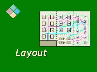
Bit 7 Datapath Bit 0 Datapath A+B C+D E+F C_REG E_REG G_REG Rhett Whatcott: v6.1: retranslate slide. Internal Logic Layout • Horizontal data flow with vertical bus alignment • Carry logic runs vertically • Bidirectional data bus longlines run horizontally • 3-state enable lines run vertically • Control lines (CE, resets, etc) are generally driven on vertical long lines
Control Signals Data Flow Data Buses Data Buses Control Signals Rhett Whatcott: v6.1: Retranslate slide. Layout for Smaller FPGAs • I/O for control signals on the top or bottom • Signals are routed vertically • I/O for data buses on the left or right • Internal layout favors horizontal data flow • Align area blocks to flow horizontally • Allow enough room for carry chains • Place block RAMs appropriately to align with arithmetic logic General guidelines for chips with 100K system gates or less:
Layout for Larger FPGAs • Use the same guidelines as you would use for smaller chips • In addition, consider the following: • Group control signals and data buses near related internal logic • High-fanout signals may be placed near the middle of the chip, for easy access to horizontal long lines For chips with 500K system gates or more: Data Flow Control Signals Control Signals
Data Bus Layout • Arithmetic functions with more than five bits typically utilize carry logic • Carry chains require specific vertical orientation • Affects both internal and I/O layout MSB LSB
B(3) A(3) B(2) A(2) B(1) A(1) B(0) A(0) Interleaved Bus Layout • Arithmetic functions involving two or more buses will benefit from interleaved pin constraints • For example: • C <= A + B; or C <= A * B;
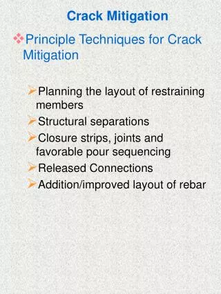
Rhett Whatcott: v6.1: Added a.k.a.’s in Heading Added first bullet Area Constraints (a.k.a. Layout, a.k.a. AREA_GROUPs) • Easiest and most effective application of floorplanning • Preferred method of floorplanning for synthesis users and large designs • Individual component names change often during synthesis, but hierarchical block names remain constant • For this to be effective, you must retain hierarchy during synthesis • Each sub-section of a large design can be constrained to an area • Area constraints allow you to provide guidance while still giving the implementation tools freedom • This is the primary floorplanning methodology for use with incremental design techniques
Area Constraints 2 1. Select the area group you want to constrain 2. Click the Assign Area button 3. Click and drag to define the area constraint • Floorplanner estimates the required area and will not allow you to select an area that is too small 1 3
Rhett Whatcott: v6.1: Retranslate slide. Area Constraint Compression • When assigning area constraints, it may be helpful to apply a compression factor for mapping • This is equivalent to the global -c option applied in map, but it only applies to an individual AREA_GROUP • Right-click the AREA_GROUP, select Edit Constraints • Constraint: Compression • Value: <%> • <%> represents the percentage of logic resources in that area constraint available for packing • Click OK
Rhett Whatcott: v6.1: retranslate. Area Constraints in UCF • Floorplanner (and PACE) area constraints create AREA_GROUP and RANGE constraints in the UCF • AREA_GROUP constraints bind instances into a group • RANGE constraints assign an AREA_GROUP to an area on the die • Syntax: • INST <hierarchical_group> AREA_GROUP = AG_<ag_name>; • AREA_GROUP <ag_name> RANGE = SLICE_XnYm:SLICE_XnYm; • AREA_GROUP <ag_name> COMPRESSION= <value>; # if applied • For example: • INST data_control_inst AREA_GROUP= AG_data_control_inst; • AREA_GROUP AG_data_control_inst RANGE =SLICE_X0Y47:SLICE_X27Y32 ; • AREA_GROUPAG_data_control_inst COMPRESSION= 90;
Rhett Whatcott: v6.1: retranslate RANGE Constraints • RANGE constraints are written for slices, block RAM, multipliers, and 3-state buffers • Range constraints will be written for each of these logic types • Slices: AREA_GROUP "AG_data_control_inst" RANGE = SLICE_X0Y47:SLICE_X27Y32 ; • Block RAMs: AREA_GROUP " AG_data_control_inst " RANGE = RAMB16_X1Y18:RAMB16_X3Y15 ; • Block multipliers: AREA_GROUP " AG_data_control_inst " RANGE = MULT18X18_X1Y18:MULT18X18_X3Y15 ; • Three state buffers: AREA_GROUP " AG_data_control_inst " RANGE = TBUF_X0Y15:TBUF_X10Y9 ;
In this situation, you are only interested in constraining the slices and 3-state buffers Hand-place the block RAMs and block multipliers Rhett Whatcott: v6.1: changed last bullet. Multiplier and Block RAM RANGE Constraints There’s only room for 4 block RAMs… but, I need room for 8! What do I do?
Multiplier and Block RAM RANGE Constraints • Comment-out the block RAM and multiplier RANGE constraints in the UCF • Hand-place the block RAMs and multipliers for optimal placement and timing • This will provide the most optimal approach to floorplanning • Control placement of block RAMs and multipliers through hand placement • Control placement of slice logic and 3-state buffers through area constraints
Rhett Whatcott: v6.1: Moved “RPM Core” section to start of Appendix. Removed “Floorplanning Flow” section. Outline • Introduction • Floorplanning Procedures • Area Constraints & I/O Layout • PACE • Summary • Appendix: • RPM Core • Overcoming MAP/PAR Limitations • Pseudo Guide File with Floorplanner • Additional I/O Considerations
Pinout and Area Constraints Editor (PACE) • PACE is a tool used to create pinout and area constraints • Constraints are written to the UCF file • The flow, look, and use are very similar to that of Floorplanner • It does not have all the capabilities of Floorplanner
Pinout and Area Constraints Editor (PACE) Device Architecture Allows area constraint specification • DesignHierarchy • Displays color-coded hierarchical • blocks Package Pins Allows pin loc specifications Package Pins Legend Design Object List Displays elements contained in the group that are selected in the Design Hierarchy window
Pin Constraints • Pin constraints most easily made using PACE Drag & Drop I/O to Package Pin window Specify I/O options in Object List window
PACE Features • To prohibit pin sites or slice sites, use the Prohibit icon in the toolbar • To allow the use of prohibited sites, use the Allow Icon • Package migration: When a design has the possibility of moving to a different package, PACE will write out prohibit constraints on incompatible pins so user can avoid reassigning I/Os • IOB Make Pin Compatible With...
Rhett Whatcott: v6.1: Changed Demo in Notes. Area Constraints 1. Select the area group that you want to constrain 2. Click the Assign Area button 3. Click and drag to define the area constraint • PACE estimates the required area and will not allow you to select an area that is too small 2 1 3
Rhett Whatcott: v6.1: retranslate slide. Area Constraint Compression • When assigning area constraints, it may be helpful to apply a compression factor for mapping • This is equivalent to the global -c option applied in MAP, but it only applies to an individual AREA_GROUP • Click Areas menu Edit Constraints, enter Constraint: Compression, Value: <%> • <%> represents the number of logic resources in that area constraint available for packing • Click Enter, click OK
Rhett Whatcott: v6.1: Moved “RPM Core” section to start of Appendix. Removed “Floorplanning Flow” section. Outline • Introduction • Floorplanning Procedures • Area Constraints & I/O Layout • PACE • Summary • Appendix: • RPM Core • Overcoming MAP/PAR Limitations • Pseudo Guide File with Floorplanner • Additional I/O Considerations
Rhett Whatcott: v6.1: Changed 2nd question. Added 3rd question. Review Questions • Will the implementation tools override any manual edits that decrease performance of your design? • What is Floorplanner beneficial for? • What is the easiest and most beneficial application of floorplanning? • After which implementation steps can you perform floorplanning? • After creating a new floorplan, which phases of implementation need to be run again? • Describe an optimal pin layout for Virtex-II/Spartan -3 devices
Review Questions • Specify the windows of the floorplanner and explain how they are used
Answers • Will the implementation tools override any manual edits that decrease performance of your design? • No