Download
1 / 22
220 likes | 338 Views
Overview of the Liquid Argon Front End electronics. Esther Ferrer Ribas (SPP/DAPNIA-CEA) On behalf of the LArg/ATLAS collaboration. CALOR 2002. 28 th March 2002. Liquid Argon Calorimeters Barrel EM ~ 110208 channels End Cap EM ~ 63744 HEC ~ 5888 FCAL ~ 3584

E N D
Overview of the Liquid Argon Front End electronics Esther Ferrer Ribas (SPP/DAPNIA-CEA) On behalf of the LArg/ATLAS collaboration CALOR 2002 28th March 2002
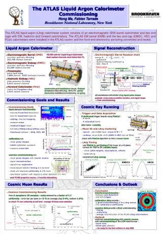
Liquid Argon Calorimeters Barrel EM ~110208 channels End Cap EM ~63744 HEC~5888 FCAL ~3584 In total ~190 K channels High energy :pp collisions @ √s = 14 TeV Large luminosity :1033/ 1034 cm-2 s-1 Large dynamic range :50 MeV – 3 TeV
Structure/segmentation • Three segmentations • Read out channels summedin projective trigger towers: Dh x Df = 0.1x 0.1
Signal tdrift= 450 ns EM 50 ns FCAL (smaller gap)
Requirements • Dynamic Range:16 bits (50 MeV – 3 TeV) • Resolution : sE/E ~ 10 % / √E 0.7 % (EM calo.) calibration < 0.25 % whole energy range • Coherent noise< 5 % of incoherent noise • Inputs for Trigger Towers: Dh x Df= 0.1x 0.1 • Limited access high reliability • Radiation levels : 5 krad and 1012 N/cm2
Radiation tests • L=10 34cm-2 s-1 significant radiation environment • Predominantely secondary particles • 10 years of operations • COTS (components of the shell) and ASICS (application specific integrated circuits) need to pass Radiation Tolerance Criteria (RTC) in order to be qualified. • Rad-tolerant tech. for main micro- electronics DMILL Standard test methods • NIEL (non ionizing energy loss) = 1.6 1012 N/cm2/10 yr (neutron irradiation) RTCNIEL = 1-3.6 1013 N/cm2 • TID (total ionizing dose)= 5 krad/10 yr (x-ray irradiation) RTCTID = 50-330 krad • SEE (single event effects)= 7.7 1011 h/cm2/10 yr (proton irradiation)
Design CALIBRATION Generate 0.2 % precision pulses 116 boards @ 128 ch CONTROLLER 40 MHz clock LVL 1 accept signal Distribute info to control and configure 116 boards TOWER BUILDER Analog sommationo of 4 layers for trigger towers Transmit analog signals to LVL 1 cavern 120 boards @ 32 ch FRONT END Amplify, shape Sum cells within each depth layer Store signals waiting for LVL 1 Digitise selected pulses, Transmit on optical fibres 1524 boards @ 128 ch
Front End Crate 38 BOARDS/CRATE 28 FEB 4 CALIBRATION 2 TOWER BUILDER 2 CONTROLLER 2 MONITORING Leak free water cooling system
Front End Boards (FEB) Input signals Preamplifiers shapers SCA ADC Gain selection logic SCA controller SPAC Output: Optical link For all calorimeters = 1600 FEBs
FEB-Preamplifiers • Amplify detector signals above noise level • 16 bit • High speed • Low impedance • Two types: • EM : warm bipolar hybrids(production of more than 50%) • Two different input impedances : 25/50 W • en = 0.4 nV/ √Hz (50 W ) • HEC: cold Ga As monolithics • (production and tests completed; yield = 84 %) • Circuits tested up to3 kGyand1014 N
FEB-Shapers • Limit the bandwidth to optimise S/N and match the 40 MHz • Bipolar CR-RC2 (to remove signal tail and limit bandwidth) • Optimisation pic vs total noise:50 ns • Tri-gain shapers(1, 10, 100)split dynamic range without degrading intrinsic detector resolution) • Rad tolerant by design (bipolar, static MOS switches) • Summing stage for the LVL1 chain • Switches for ‘‘hot’’ cells • Full production completed. • Noise: high gain=850 µV • medium=390 µV • low=250 µV • Integral non-linearity: 0.5 %
Switched Capacitor Array (SCA) • Samples @40Mhz the 3 gains of 4 calorimeter channels • 16 analog channels with 144 cells • 12 channels to store the signal • 4 channels store a reference level • subtraction of closest reference channelreduction of noise • Dynamic range needed > 12.5 bits • Store the 5 samples up to 100 µs • Read @5MHz for ADC conversion • Simultaneous Write and Read operations • DMILL • 50 Krad, 2 1013 Ncm-2 • Noise = 300 V • Fixed sequence noise < 0.2mV • Dynamic range =13.3 bits • Cell/cell gain variation < 0.02% • Drift < 3 mV/ms • Integral non linearity < 0.1% • Starting production
Test Beam EM • 1 pre-series module and 4 series modules: 2 barrel, 2 End Cap • Final electronics tested with 6000 channels • 50 FEB, 12 calib, 1 TBB tested • Boards with all functionalities but not completely rad-hard HEC • 12 pre-series module and 24 series modules • 400cold channels
Test Beam EM Free gain performance • Final density: 128 channels/FEB • Full dynamic range : (50 MeV-3 TeV) • Noise:~140 MeV(high gain) and ~240 MeV (medium gain) standard electron cluster • Coherent noise: 5-7% • Power dissipation: 0.7 W/ch • Medium gain predefined sample in time < threshold high gain • Threshold in medium gain is respected • Dynamic range in high gain is well used Test Beam results Dirk’s presentation
CALIBRATION BOARD • Generates 0.1% precision • calibration pulses • 9000 components • Sensitivity to various COTS • Injected charge effort develop op-amp • Static low-offset op-amp (~10 µV) • DAC in rad-hard technology DMILL Irradiated to 2kGy and 1014N : OK
CALIBRATION BOARD Uniformity : 0.11 % Crosstalk < 0.1 %
TOWER BUILDER BOARD • 32 trigger towers/board (120 boards) • Correction poles to get all signals at tpeak = 35 ns • Programmable delays to align pulses before summing • Prediction of the components implies a good knowledge of the electronic chain and detector • ±3 ns, 5 % • Noise =300 MeV; saturation • Irradiated :2 KGy and 3 10 13 N • Boards validated for production Analog summation of the different layers to form LVL1 towers Ouput cables (70m) Front End to LVL1 cavern ordered crosstalk < 0.2 %
CONTROLLER BOARD Load, update, check different registers and parameters for all different front end boards (clock, LVL1, bunch crossing…) Time Trigger Control (TTC) 2 fibers for reliability Serial control link SPAC Special bus designed : SPAC bus Read and write lines doubled Speed 10 Mb/s October 02: 2 final boards
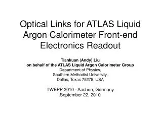
Optical link Link to transfer FEB’s data to the Read Out Driver system • Radiation resistant Gigabit ethernet speed digital optical link : HP Glink chosen • Effort on low error rate system • Front end crate test autumn 02 : Glink ready • Extensive radiation studies : 3 kGy, 5 1013N SEE : 0.47 bit flip/link/hr 8 hrs dead time in 10 yrs LHC
Conclusion and Perspectives • 6000 channels have been already used in test beam Full dynamic range Expected noise validity of the technical choices Calibration and specifications fulfilled • System crate test with all final radiation-hard boardsautumn 02 • Future Apr 03 : production of 1650 FEB Oct 04 : assembly complete Feb 05 : installation complete