Download
1 / 1
10 likes | 181 Views
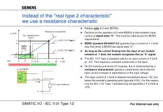
Instead of the "real type 2 characteristic" we use a resistance characteristic. Relates only to 2-wire BEROs. Decisive for the operation of 2-wire BEROs is the module‘s input current at signal state "0" . This must be rated as per the BERO requirements.

E N D
Instead of the "real type 2 characteristic" we use a resistance characteristic • Relates only to 2-wire BEROs. • Decisive for the operation of 2-wire BEROs is the module‘s input current at signal state "0". This must be rated as per the BERO requirements. • BERO standard EN 60947-5-2 specifies that a current of 1.5mA may flow when a BERO has signal state "0". • As long as the current flowing into the input of our module remains at 1.5mA, the module recognizes this as "0" signal. • The IEC 1131 Type 2 standard calls for an input current of 2mA at +5V. This requires a constant-current sink in the input. • On S5 modules and some S7 modules, this is implemented by a resistance characteristic (passive components) which lets the input current increase in dependence on the input voltage. • The input current of 1.5mA is attained somewhere above +5V, but below the module‘s operating point (typically 9.5V). For this reason, only the IEC 1131 Type 1 standard may be specified (I 0.5mA at +5V). Resistance characteristic IE [mA] Typ. operating point (9.5V) Imin to IEC 1131 Type 2 7 6 BERO- Norm I 1.5mA Imin to IEC 1131 Type 1 2 1.5 0.5 0 5 -30V 30 11 13 15 24 L+[V] “0“ “1“ 2- wire BERO L+ I ==> "0" signal I 1.5mA PLC input resistance M For internal use only