Download
1 / 29
290 likes | 494 Views
http://aero-comlab.stanford.edu/. Challenges and Complexity of Aerodynamic Wing Design. Kasidit Leoviriyakit and Antony Jameson Stanford University Stanford CA. International Conference on Complex System (ICCS2004) Boston, MA, USA May 16-21, 2004. Airplane is a very complex system.

E N D
http://aero-comlab.stanford.edu/ Challenges and Complexityof Aerodynamic Wing Design Kasidit Leoviriyakit and Antony Jameson Stanford University Stanford CA International Conference on Complex System (ICCS2004) Boston, MA, USA May 16-21, 2004
Airplane is a very complex system. Flow is complex. • Everything has to work together: • Aerodynamic • Propulsion • Structure • Control
The Navier-Stokes Equation Solving the Navier-Stokes is extremely difficult.
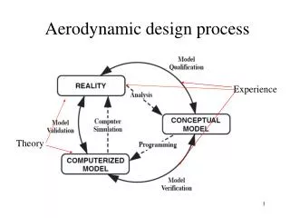
Levels of CFD Automatic Design HIGHEST • Integrate the predictive capability into an automatic design method • that incorporates computer optimization. Interactive Calculation • Attainable when flow calculation can be performed fast enough • But does NOT provide any guidance on how to change the shape if performance is unsatisfactory. Flow Prediction • Predict the flow past an airplane or its important components in different flight regimes such as take-off or cruise and off-design conditions such as flutter. • Substantial progress has been made during the last decade. LOWEST
Optimization and Design using Sensitivities Calculated by the Finite Difference Method f(x)
The need for a number of flow calculations proportional to the number of design variables Too Expensive Disadvantage of the Finite Difference Method Using 2016 mesh points on the wing as design variables 2017 flow calculations ~ 2-5 minutes each (Euler) Boeing 747
Application of Control Theory GOAL : Drastic Reduction of the Computational Costs Drag Minimization Optimal Control of Flow Equations subject toShape(wing) Variations e.g. Minimize CD
One Flow Solution + One Adjoint Solution Application of Control Theory (Adjoint) (Gradient) 2016 design variables
Advantage of the Adjoint Method: • Gradient for N design variables • with cost equivalent to two flow solutions • Minimal memory requirement in • comparison with automatic differentiation • Enables shapes to be designed as free surface • No need for user defined shape function • No restriction on the design space 2016 design variables
Flow solution Adjoint solution Gradient calculation Repeated until Convergence to Optimum Shape Sobolev gradient Shape & Grid Modification Outline of the Design Process
Key issue for successful implementation of the Continuous adjoint method. Sobolev Gradient Continuous descent path
Computational Costs with N Design Variables(Jameson and Vassberg 2000) - N~2000 - Big Savings - Enables Calculations on a Laptop
Redesign of the Boeing 747 Wing at its Cruise Mach Number Constraints : Fixed CL = 0.42 : Fixed span-load distribution : Fixed thickness 13% wing drag saving (5 minutes cpu time - 1proc.) ~6% aircraft drag saving Euler Calculation baseline redesign
Redesign of the Boeing 747 Wing at its Cruise Mach Number Constraints : Fixed CL = 0.42 : Fixed span-load distribution : Fixed thickness 10% wing drag saving (3 hrs cpu time - 16proc.) ~5% aircraft drag saving RANS Calculations baseline redesign
We can fly faster at the same drag. Redesign of the Boeing 747 Wing at Mach 0.9 “Sonic Cruiser” Constraints : Fixed CL = 0.42 : Fixed span-load distribution : Fixed thickness RANS Calculations Same CD @Cruise
Planform and Aero-Structural Optimization Boeing 747 at CL ~ .47 (including fuselage lift ~ 15%) Induced Drag is the largest component
Wing planform modification can yield larger improvements BUT affects structural weight. Wing Planform Optimization Simplified Planform Model Can be thought of as constraints
Choice of Weighting Constants Minimizing Maximizing Range using
Planform Optimization of Boeing 747 Constraints : Fixed CL=0.42 Baseline Redesign Longer span reduces the induced drag 2) Less sweep and thicker wing sections reduces structure weight 3) Section modification keeps shock drag minimum Over: Drag and Weight Savings
Pareto Front: “Expanding the range of the Designs” Use multiple a3/a1 ==> Multiple Optimal Shapes Boundary of realizable designs
Conclusion • Aerodynamic wing design is very complex due to the complexity nature of flow around the wing. • By exploring the adjoint method, aerodynamic wing design can be carried out rapidly and cost efficiently. Pay-Off • Enables aerodynamic design by a small team of experts • focusing on the true design issues. • Significant reduction in time and cost. • Potential for superior and unconventional designs.
Acknowledgement • This work has benefited greatly from the support of the Air Force Office of Science Research under grant No. AF F49620-98-1-2002. • Optimization codes are developed by Intelligent Aerodynamic Inc. • http://aero-comlab.stanford.edu/
Automatic Design Aero-Structural Design Aerodynamic Design Process • Problems: • Need high level of expertise to improve the design. • Re-generating mesh is time consuming. Preliminary Design Level
Improved MDD Redesign of the Boeing 747: Drag Rise( Three-Point Design ) Constraints : Fixed CL = 0.42 : Fixed span-load distribution : Fixed thickness Improved L/D RANS Calculations benefit Lower drag at the same Mach Number Fly faster with the same drag benefit
Planform and Aero-Structural Optimization • Design tradeoffs suggest an multi-disciplinary design and optimization Maximize Minimize Planform variations can further maximize VL/D but affects WO
Aerodynamic Design Tradeoffs If we want to have large drag reduction, we should target the induced drag. Change span by changing planform Design dilemma Di decreases Increase b WO increases
Additional Features Needed • Structural Weight Estimation • Large scale gradient : span, sweep, etc… • Adjoint gradient formulation for dCw/dx • Choice of a1, a2, and a3 Use box wing to estimate the structural weight. Large scale gradient • Use summation of mapped gradients to be large scale gradient
Planform Optimization of MD11 Constraints : Fixed CL=0.45 Baseline Redesign