Download
1 / 35
350 likes | 456 Views
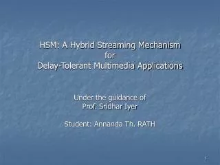
HSM : A Hybrid Streaming Mechanism for Delay-Tolerant Multimedia Applications. Under the guidance of Prof. Sridhar Iyer Student: Annanda Th. RATH. Key words. Delay tolerant Applications Client specifies the playback time Service must be done according to client requirements

E N D
HSM: A Hybrid Streaming Mechanism for Delay-Tolerant Multimedia Applications Under the guidance of Prof. Sridhar Iyer Student: Annanda Th. RATH
Key words • Delay tolerant Applications • Client specifies the playback time • Service must be done according to client requirements • Pure Streaming Mechanism (PSM) • There is only one streaming server at the source • Server is responsible for serving all the requests • Hybrid Streaming Mechanism (HSM) • Streaming from strategically chosen relay node in stead of central (source) server • Data flow is divided into two parts: FTP flow from source to selected relay node and streaming flow from selected relay node to client
Problem Definition • Objective (Goal) • Improving the performance of streaming service • Maximizing the number of serviced clients • Improving the delivered stream rate at the client • Maximizing the bandwidth utilization in the backbone network • Reducing the traffic in the network
Solution Outline • Proposed a Hybrid Streaming Mechanism (HSM) • Advantage of HSM • Improving the performance of streaming service • Increasing the number of serviced clients • Maximizing the bandwidth utilization • Reducing the work load at central server as well as the traffic in the network • Where HSM can be used? • Streaming in the internet • Distance Education Program • Corporate Training
Motivation • Why HSM and not PSM? • Disadvantages of PSM • Clients occupy entire links in the path while streaming, for the duration of the stream • For the duration that a client is using the links, others who are sharing the link (s) in the path, are not able to use the link (s) • Fewer users are serviced • Links can be underutilized
Motivating Example HSM ! S 448 Kbps 768 Kbps 50 mns PSM ! 1 192 Kbps 512 Kbps 512 Kbps 75 mns 3 2 512 Kbps 384 Kbps 384 Kbps 8 7 5 256 Kbps 512 Kbps 512 Kbps 768 Kbps 384 Kbps 768 Kbps 4 9 6 C9 C8 C7 384 Kbps Central server 480Kbps 384 Kbps 512 Kbps 512 Kbps 466Kbps 384 Kbps 256 Kbps 11 12 Relay node C12 C11 C10 10 240Kbps 256 Kbps 384 Kbps 384 Kbps 256 Kbps 480 Kbps 256 Kbps Region node 384 Kbps 512 Kbps 128 Kbps C14 C13 C1 C2 C3 C6 C5 C4 Client 320 Kbps 240 Kbps 320Kbps 480 Kbps
Motivating Example: Cont.d Details of client C1
Assumption • Links have dedicated bandwidth provisioned for the given application • Selected intermediate nodes have the streaming capability • Multicasting is also supported in the given network topology
Functional Overview of HSM • HSM’s components • Delivered stream rate calculation • Streaming point selection • Content transferring and streaming HSM! Content is storing PSM! Client SP
S n SP 1 B1 Bn+1 dn d1 L1 C Lm+1 1 m Delivered Stream Rate Calculation • Rate calculation • Find the weakest link along the path. • Client delay tolerance. • Streaming duration
Streaming Point Selection • Selection strategies • At the node with maximum outgoing links • If the delivered stream rate is less than the weakest link in the path from source to region node • At the node below the weakest link • If the delivered stream rate is greater than the weakest link in the path from source to region node
Reasoning for the selection strategies S 768 Kbps 1 512 Kbps 512 Kbps 3 2 512 Kbps 384 Kbps 384 Kbps 8 7 5 256 Kbps 512 Kbps 512 Kbps 768 Kbps 384 Kbps 768 Kbps 4 9 6 Central server C9 C8 C7 384 Kbps 384 Kbps 512 Kbps 512 Kbps 384 Kbps 256 Kbps Relay node 11 12 C12 C11 C10 10 256 Kbps Region node 384 Kbps 384 Kbps 256 Kbps 256 Kbps 384 Kbps 512 Kbps 128 Kbps C14 C13 Client C1 C2 C3 C6 C5 C4 448 Kbps 224 Kbps
Note: Streaming Point Selection • According to the two strategies, there are two possible places for streaming point: • (i) at the node, which has the maximum outgoing links and • (ii) at the node below the weakest link from the source to region node • Given the random nature of the clients’ request and its requirements, it is hard to predict the delivered stream rate at the client, it may happen that some time, delivered stream rate is less than the weakest link and some time it is greater than the weakest link • In order to cover the two cases, in HSM, we deploy at least two streaming points for one region, one at the node which has the maximum outgoing links and other at the node below the weakest link • Note that one streaming point may serve more than one region
Content transferring and streaming • Use FTP to transfer streaming content to the selected SP • Content is temporarily stored at the SP for a period equivalent to the streaming duration (SD) • Time To Live of Content (TTLC) is extended if new request arrives • TTLC expires if there is no new request within SD
S n SP 1 B1 Bn+1 dn d1 L1 C Lm+1 1 m Time to Transfer the Content • Time to transfer content using FTP
Caching Memory Management at Relay Node (s) • Memory requirement at relay node (s) • A step-by-step approach to find out the caching memory size at the relay node (s) • Find the number of sub trees rooted at SP. Let this be N • Find the number of regions in each sub tree. Let this number be R • For each sub tree • Find the weakest link for region j, Bminj • Find the max of weakest link across all regions R, Wi= Max (Bminj), j=1, ..,R and i= 1, …, N • The maximum amount of data that can flow in the sub tree i = Wi*SD, where SD is the stream duration • Let FSmax be the maximum file size across all content files stored at S. Since clients in the regions can specify delay tolerance, we must find the largest file size that need to be cached. Thus, the cache size for a sub tree is given by: Max(Wi * SD, FSmax) • The cache size at streaming point in node g, considering all the sub trees is given by:
Time To Live of Content • How to choose TTLC and how to extend it • TTLC is equal the streaming duration plus client delay tolerance • It is extended if there is a new request within its life time • The content is removed from the cache when its TTLC expires Tc : is the TTLC of the current content tk : is the time when client k’s request arrives CDk :is the delay tolerance of client k Extension of TTLC = Tc+ CDk-(Tc-tk)+SD
HSM based Tool Architecture • HSM based Tool components Top Level HSM’s Architecture Operation Module Outputs Module Inputs Module Network topology and specific link bandwidth Delivered Stream Rate Calculation + Weakest link along the path detection + Stream Rate Calculation + Delivered stream rate at the clients 1 Clients’ requirements (Delay Tolerance, Minimum Rate) + Streaming Point Position (Intermediate Node number) Streaming Point Selection + Weakest link along the path detection + Node with the maximum outgoing links detection 2 + Link Busy Period along the path from source to client. + TTLC Object name and the region that client belongs to Content Transferring and streaming + Calculation time to transfer the content across all the links in the path + Setting the TTLC 1: Delivered Stream Rate 2: Streaming Point Position
Simulator’s Architecture (Matlab Implementation) Simulator’s Architecture Topology Generator Static Network Topology . Static network topology . Number of nodes in the network. . Number of links in the network . Link bandwidth . Level Number . Number of nodes in the network Topology Generator Module . Level Number (The deep of the network) Link Bandwidth Generator Module . Link bandwidth interval (Min - Max) PSM Module (1) . Client’s request pattern generator . Client’s requirements generator . PSM like operation module . Number of serviced client calculation module . Percentage of stream rate improvement calculation module HSM module (2) . Client’s request pattern generator . Client’s requirements generator . HSM like operation module . Number of serviced client calculation module . Percentage of stream rate improvement calculation module Outputs . Number of serviced clients . Percentage improvement of client stream rate
Performance Evaluation of HSM • Simulation Parameters • Play out duration is set to 2 hrs • Observation period is 4 hrs • Queuing and propagation delay is set to zero • Arrival rate of clients’ requests is varied from 1 to 30 per minute • Scenarios • 100 differences topologies are used, divided into two different classes. • Class 1: 50 topologies, with the bandwidth in the range (256-768 Kbps) • Class 2: 50 topologies, with the bandwidth in the range (128-256 Kbps) • Gnutella like network topology has been used, it consists of 510 nodes with 14 levels • Performance evaluation parameters • Number of serviced clients • Percentage of delivered stream rate improvement for a client as compared with its minimum rate requirement
Number of serviced clients Vs. Client Delivered Stream Rate (Class 1)
Impact of clients’ delay-tolerance on System Performance (Class 1) HSM PSM
Number of serviced clients Vs. Client Delivered Stream Rate (Class 2)
Number of serviced clients Vs. Client Delivered Stream Rate (Gnutella)
Analysis of Results • Performance of HSM depends on two factors • Network topology with specific link bandwidths • Clients’ requirements • HSM performs well with class1 network • Because of FTP property built in HSM • With class 2 network • HSM performs slightly better than PSM
Related Work • Related work • Initial-latency (delay) is the main issue • Considers streaming service as a real time application • Content replication • Object placement, proxy caching • Resource Sharing • batching, patching, interval caching, broadcasting • Caching location problem
Conclusions & HSM Extensions • Conclusions • In general, HSM performs better than PSM for the number of serviced users. • HSM serves more users (on the average 40%) as compared with PSM. However it performs slightly less (on the average 5%) than PSM for the streaming rate improvement. • HSM can be deployed in the Distance Education Program or streaming service in the Internet. • HSM extensions • Admission Control. • Converting from Static to dynamic link bandwidth. • Optimal Placement of the streaming point.
References • “Determining the Optimal Placement for Web Proxy Cache Servers Considering Latency in the Network”, Vikram Tiwari, Venkataramanam, Srinagesh Gavirneni • “Caching Location Problem”, P.Krishnan, Danny Raz, Yuval Shavitt, IEEE/ACM Transaction on Networking, VOL.8 & NO.5, October 2000. • “Batch Patch Caching for Streaming Media”, Pascal Frossard and Olivier Verscheure, IEEE Communications Letter, VOL.6, NO.4 • “Proxy that Transcode and Cache in Heterogeneous Web Client Environment”, Aameek Singh, Abhishek Trivedi, Krithi Ramamrithan, IIT Bombay. • “Streaming approach over internet: Approaches and directions”, W. Z. Y.-Q. Z. a. J. M. P. Depeng Wu, Yiwei Tomas Hou. IEEE Transaction on circuit and system for video technology, 11(3):282{300, March 2001. • “Efficient bandwidth resource allocation for low-delay multiuser video streaming”, W. W. Guang Ming Su. IEEE Transaction for Circuits and Systems for Video Technology, 15(9):1124{1137, September 2005. • “Multipath routing for video delivery over bandwidth-limited network”, S.-H. G. C. Victor O.K, Li Jiancong Chen. IEEE Trans, 22(10):1920{1932, 2004. • “Optimal chaining scheme for video-on-demand applications on collaborative networks”, C.-L. C. Te-Shou Su, Shih-Yu Huang and J.-S. Wang. IEEE Transactions on multimedia, 7(5):972{980, October 2005.
Thanks! Questions?
Impact of client’s delay tolerance • Why performance of HSM increases when client’ delay tolerance increases? T1 Ts1 T2 Tf1 T2 T2 C1 (T1, Ts1, Tf1) C2 (T2, Ts2, Tf2 ) C2’s delay tolerance
Delivery Stream Rate Calculation S 768 Kbps 50 mns • assuming the streaming duration is 2 hours • 256 Kbps, 30 minutes delay tolerance • (S-1-2-4-10-C1) is the path from server to C1. • Min (768, 512, 256, 384, 256) = 256 Kbps • 30*60*256/2*3600 + 256 = 320 Kbps 1 512 Kbps 512 Kbps 75 mns 3 2 512 Kbps 384 Kbps 384 Kbps 8 7 5 256 Kbps 512 Kbps 512 Kbps 768 Kbps 384 Kbps 768 Kbps 4 9 6 C9 C8 C7 384 Kbps 384 Kbps 512 Kbps 512 Kbps 384 Kbps 256 Kbps 11 12 C12 C11 C10 10 240Kbps 256 Kbps 384 Kbps 384 Kbps 256 Kbps 256 Kbps 384 Kbps 512 Kbps 128 Kbps C14 C13 C1 C2 C3 C6 C5 C4
Caching requirement at relay nodes • Let SD= 2hours (7200 seconds) • FSmax= 2 GB. • Let node 2 be the chosen streaming point. • We calculate the cache size at node 2 as follows: • Number of sub trees rooted at node 2, N=3 • For sub tree 1, Number of regions, R=1; • Bmin1= Min (384,512)=384 • Max(Bmin1)= 384. • For sub tree 2, Number of regions, R=2; • Bmin1= Min (256, 384) =256; • Bmin2= Min (256, 256) =256; • Max (Bmin1, Bmin2)= (256, 256)= 256. • For sub tree 3, Number of regions, R=1; • Bmin1= Min (384, 512, 512)=384; • Max (Bmin1) = 384 • Cache size at node 2 (CS2) = Max (384*7200, 2 GB) + Max (256*7200, 2 GB) + Max (384*7200, 2 GB) = 7.36 Gb
Time To Live of Content • Example: • Let C1 with 30-minute delay tolerance requesting a stream with 2 hours duration. • TTLC for this stream is T = 30 + 120 =150 minutes. • Let a new request for the same stream comes from client C2 at t=90 later • C2’s delay tolerance is 90 minutes. • The extended value of TTLC for the stream is: 150 + 90 - (150 - 90) + 120. Thus, the content is alive till t=300 minutes.
Example: Admission Control Admission Control Window time S 768 Kbps • Determine the threshold value (by CSP) • Find the mode value across the collected samples • If mode is less than the threshold value • Apply the median as the common stream rate to all the clients • Otherwise, use mode 1 512 Kbps 512 Kbps 3 2 512 Kbps 384 Kbps 384 Kbps 8 7 5 256 Kbps 512 Kbps 512 Kbps 768 Kbps 384 Kbps 768 Kbps 4 9 6 C9 C8 C7 384 Kbps 384 Kbps 512 Kbps 512 Kbps 384 Kbps 256 Kbps 11 12 C12 C11 C10 10 240Kbps 256 Kbps 384 Kbps 384 Kbps 256 Kbps 256 Kbps 384 Kbps 512 Kbps 128 Kbps C14 C13 C1 C2 C3 C6 C5 C4