Download

1 / 68
680 likes | 791 Views
This research focuses on an innovative approach to circuit equivalence checking, leveraging appearance-based techniques to transform combinational circuits into equivalent forms without the need for traditional BDD constructions. The methodology involves observing the circuit appearances, applying rewiring techniques, and implementing correction rules to verify functionality equivalence between a golden circuit and a revised circuit. Results demonstrate optimized circuit performance, showcasing the potential of error injection-based rewiring and circuit simplification for future work in this domain.

E N D
Appearance-based Equivalence Checking Speaker: Ching-Yi Huang Advisor: Chun-Yao Wang Date: 2011/05/06
Outline • Introduction • Approach • Methodology • Overview • Observation and Transformation Rules • Error Injection-based Rewiring (EIR) • Circuit Optimization • Flow Chart • Implementation • Correctness Verification • Circuit Simplification • Experiment Results • Future work
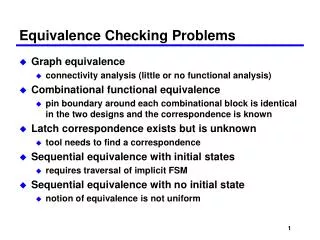
Introduction • What is equivalence checking? • Given: • Two combinational circuits. Golden circuit and revised circuit. • Objective • Check whether the functionality of two given combinational circuits are equivalent.
Introduction • Functionality equivalence I1 O1 C1 Im On o1 C2 on
Introduction • Traditional methods • Truth table • ATPG-based • BDD-based • SAT-based
Our Approach • Appearance-based approach • Don’t build BDDs • If two circuits are equivalent, there should be a rule to transform their appearance into the same one.
Our Approach • Given: • Two combinational circuits. Golden circuit and revised circuit. • Objective • Observe their appearances • Transform the appearance (by rewiring techniques) of one circuit into a new circuit which is the same as the other according to the rules.
Outline • Introduction • Approach • Methodology • Overview • Observation and Transformation Rules • Error Injection-based Rewiring (EIR) • Circuit Optimization • Flow Chart • Implementation • Correctness Verification • Circuit Simplification • Experiment Results • Future work
Overview An action per round For eliminating the rectification networks
Structure • AIG = AND-Inverter Graph • DAG = Direct Acyclic Graph • Two Inputs AND gate node • Inverter on the edge B C F A
Outline • Introduction • Approach • Methodology • Overview • Observation and Transformation Rules • Error Injection-based Rewiring (EIR) • Circuit Optimization • Flow Chart • Implementation • Correctness Verification • Circuit Simplification • Experiment Results • Future work
Observation • Examples B B C A F F A C
Observation • Look at the nodes of the same level B B C A F F A C
Observation • Create necessary node/ Delete surplus node B B C A F F A C B A C
Observation • Create transform ID (TID) 1 1 1 B B A A F F A 2 A C 2 C
Observation • Next level 1 1 F F A 2 2
Observation • Observe next level 1 1 F F A 2 2
Observation • Observe next level • Rewiring 1 1 F F A 2 2
Observation • Observe next level • Gate Replacement (change phases) 1 1 v v F F 2 2
Rule & Decision • So… let us conclude the rules • 1. Create node • Add wire when patch it • 2. Delete node • Remove wire • 3. Remove wire • 4. Change fanin • Remove wire • Add wire (could be more smart) • 5.Gate replacement
Rule & Decision • 1. Create node B B A A F F A 1.Create node C 2. Add wire A C
Rule & Decision • 2. Delete node B B C C F F A A Remove wire C
Rule & Decision • 4. Change Fanin 1 1 F F 2 3
Rule & Decision • 4. Change Fanin 1 1 F F 2 3 3
Outline • Introduction • Approach • Methodology • Overview • Observation and Transformation Rules • Error Injection-based Rewiring (EIR) • Circuit Optimization • Flow Chart • Implementation • Correctness Verification • Circuit Simplification • Experiment Results • Future work
EIR • Error Modeling • Removal • Addition • Replacement • Propagate fault • Find TAs • Choose destination • Rectification
Model the errors (AIG format) • Remove wire
Model the errors (AIG format) • Add wire a a a a b b
Model the errors (AIG format) • Replacement
Model the errors (AIG format) • Replacement
EIR • Destination Ⅱ Ⅰ Ⅲ error effect . . . . . .
EIR Algorithm • Region I/II • DON/DOFF = AND(TA) • If the error effect propagated to gd is 1/0, the corrected function for the error effect is • If the error effect propagated to gd is 0/1, the corrected function for the error effect is • If both 1/0 and 0/1 error effects are propagated to gd, the corrected function is either or
EIR Algorithm • Region III gdg(TA)= the cofactor of gd with respect to TA in good circuit • DON: • DOFF: • Corrected function: or
Rectification Issue • Choose where? • Considering that we want to eliminate the rectification networks in the future…
Choose the PO as destination • Choose the PO as destination!? • PO is the common dominator! • How about the multi-PO circuit? B C D A E F G
Partition • Multiple POs C1 i1 P1 i2 P2 i3 P3 i4
Partition • Partition by POs • How about the overlapping part? • Duplicate the common part in both circuits! C1 i1 P1 i2 P2 i3 P3 i4
Partition • Partition and duplicate C1 i1 i1 P1 P1 i2 i2 P2 P2 i3 i3 P3 P3 i4 i4 C2
Partition • Partition and duplicate i1 C1-1 P1 i2 i2 C1-2 P2 i3 i3 P3 C1-3 i4 i1 C2-1 P1 i2 i2 C2-2 P2 i3 i3 P3 C2-3 i4
Outline • Introduction • Approach • Methodology • Overview • Observation and Transformation Rules • Error Injection-based Rewiring (EIR) • Circuit Optimization • Flow Chart • Implementation • Correctness Verification • Circuit Simplification • Experiment Results • Future work
Optimization • Node-merging w1 w1 w2 w2 nt nt w3 w3 w4 ns ns w4
Outline • Introduction • Approach • Methodology • Overview • Observation and Transformation Rules • Error Injection-based Rewiring (EIR) • Circuit Optimization • Flow Chart • Implementation • Correctness Verification • Circuit Simplification • Experiment Results • Future work
Flow chart Start N If now_leveli < max_level optimization End Y Collect the node of level i Mark the nodes Y N Are all nodes dealt with? Observe one node in the same level Decide the action now_level ++ EIR
Flow chart (EIR) Start Receive Action Model error Fault Activation Fault Propagation Rectification & rewiring Re-levelization Circuit Simplification End
Flow Chart Receive Action Start N Model error If now_leveli < max_level optimization End Y Collect the node of level i Fault Activation Mark the nodes Fault Propagation Y N Are all nodes dealt with? Observe one node in the same level Rectification & rewiring Decide the action now_level ++ Re-levelization Circuit Simplification
Outline • Introduction • Approach • Methodology • Overview • Observation and Transformation Rules • Error Injection-based Rewiring (EIR) • Circuit Optimization • Flow Chart • Implementation • Correctness Verification • Circuit Simplification • Experiment Results • Future work
Correctness Verification • Two-stage: • Stage 1: • Everywhere and every case • Recover the circuit every time • Stage 2: • Focus on checking the correctness in the condition that there are some new nodes in the circuit • No recovery • Need threshold • Verify by SIS tool (output and original)
Correctness Verification • Removal • Stage 1 • For every node(source) to its every fanout(target) • Remove the wire(source->target) • Recover the circuit • Stage 2 • For every node to its every fanout (but not include the new fanouts patched in this round) • Remove the wire(source->target)
Stage 1 B B B B B B A A A A A A F F F F F F C C C C C C
Stage 2 Rectification network Rectification network B B B B A A A A F F F F C C C C Rectification network