Download
1 / 13
130 likes | 234 Views
Explore the critical issue of cooling for APD stability at CERN. Learn about APD gain, XTAL response, and thermal requirements to minimize energy resolution correction. Discover strategies for stable data taking, system understanding, and heat transfer dynamics.

E N D
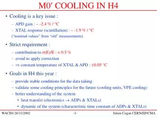
M0 COOLING IN H4 • Cooling is a key issue : • APD gain : ~ -2.4 % / C • XTAL response (scintillation) : ~ -1.9 % / C (“nominal values” from “old” measurements) • Strict requirement : • contribution to (E)/E : < 0.5 % • avoid to apply correction • constant temperature of XTAL & APD : 0.05 C • Goals in H4 this year : • provide stable conditions for the data taking • validate some cooling principles for the future (cooling units, VFE cooling) • better understanding of the system • heat transfer (electronics ADPs & XTALs) • dynamic of the system (characteristic time constant of ADPs & XTALs) Julien Cogan CERN/EP/CMA
OUTLINE • M0 cooling : • mechanic • cooling units & circuits • next year strategy • Thermal stability during the data taking : • water circuits • environment • APDs (capsules) • failures • Thermal studies (covered in next talks) • heat transfer, temperature rise when electronics is turned on (P. Baillon) • temperature steps (Roberto Salerno, J. Cogan) Julien Cogan CERN/EP/CMA
COOLING MECHANIC (1) • Bare module = fully equipped module with 400 crystals • final grid (cooled through 9 holes drilled along z) • thermal shield( attached to the APD connector mechanical assembly 10 lines) • special thermal screen(2 layers of pipes around the 5 faces of the crystal basket) • module isolated from its support by 4 cooled blocks of aluminum • module isolated from the environment by 4 cm of rock wool Julien Cogan CERN/EP/CMA
COOLING MECHANIC (2) • Electronics = 20 VFE cards 10 blocks 100 channels • FPPA + ADC + GLINK (+DRIVER) ( ~2.5W/Ch) • copper housing manufactured to compensate for the different height of the components (minimal thickness = 0.7 mm) • 0.5 mm thick gap pad between the copper housing and the components + contact at the bottom of the cards (1 mm thick 4 mm wide gap pad) • 10 lines of cooling pipes ( 3/4 mm) brazed on the copper housing Julien Cogan CERN/EP/CMA
COOLING UNITS & CIRCUITS (1) Julien Cogan CERN/EP/CMA
COOLING UNITS & CIRCUITS (2) • Regulating circuit : flows through the grid and then on the thermal shield • q = 0.22 l/s (80 % of nominal flow) • T(OUT-IN) typically few 1/100 C • water regulation and circulation done by a LAUDA • Ambient circuit : flows in the thermal screen and on the insulating al. blocks • q 0.1 l/s • T(OUT-IN) typically few 1/10 C • water regulation and circulation done by a LAUDA • Power circuit : cools the VFE boards • q 0.14 l/s (M0) (+ ~0.14 l/s by pass) • T(OUT-IN) typically few 1/10 C ; P 1.5 bar • water under pressure (P~2.5 bar) • water regulation and circulation : • heat removal : chilled water + heat exchanger • water regulation : heater (max = 2kW) controlled by a regulator (PID) Julien Cogan CERN/EP/CMA
NEXT YEAR STRATEGY • Cooling circuit : only one circuit • cooling unit similar to this year power circuit • work is in progress (dimensioning of the circuit, buying of the elements, control loop) • Cooling of the electronics (is being decided) • from cooling point of view : same principle as this year (?) • mechanically : cooling bars instead of brazed tubes (?) • introduction of a mother board and additional kapton cables between the VFE and the APD connector 18.8 C 14.5 C Mixed water PID 17.8 C 17.8 C Simplified schematic of the foreseen cooling unit Julien Cogan CERN/EP/CMA
SHORT-TERM STABILITY : WATER (1) Regulation circuit Power circuit INLET 0.05 C INLET 1 week OUTLET OUTLET Julien Cogan CERN/EP/CMA
LONG-TERM STABILITY : WATER 2 o’clock jumps Power circuit Regulation circuit Power cut Lauda remote control off 0.05 C ? INLET INLET 3 months (aug/sept/oct) OUTLET OUTLET Julien Cogan CERN/EP/CMA
STABILITY : ENVIRONMENT MEM (output water temperature) Room (measured on a copper plate near the module) out of water 1 C 2 C 3 months (aug/sept/oct) Ambient circuit (inlet & outlet) Primary circuit (inlet) 0.5 C 2 C Julien Cogan CERN/EP/CMA
STABILITY : CAPSULES LV block A 0.1 C 3 months (aug/sept/oct) LV block B 0.1 C Julien Cogan CERN/EP/CMA
STABILITY : FAILURES • Laudas remote control : • setting of the Lauda controlled by a computer (to be able to change the temperature form the control room) • induce instabilities and mysterious jumps ( ~0.02C) at 2 AM (related to computer activity ?) • remote control disabled after 2nd temperature step (16/08/02) : small change in the setting (~0.02C ) • Chilled water failures : • Pb with chilled water in the area happened twice (last for less than 1 day) : • 12/08/02 • 23/09/02 • induced a rise of temperature of the power circuit (~1C ) • induced a small rise of temperature on the APD Julien Cogan CERN/EP/CMA
CONCLUSION • STABILITY : • Generally good thermal stability during all the data taking : • constant temperature of the cooling water well within 0.05C • constant temperature of the capsule well within 0.1C • Probably no need to correct for temperature effect • Very few failures • M0’ cooling system : • validation of some principles for : • cooling units • VFE cooling • give confidence for the future Julien Cogan CERN/EP/CMA