EMISSION PROBE PARTS
EMISSION PROBE PARTS. Cap Tube with Swagelok Cap SS-600-C (if keeping probe installed) Or Plug Adapter with Swagelok Plug SS-600-P (if probe is removed). 3/8 Nut-Ferrule sets (Swagelok SS-600-NFSET). TUBE: 3/8” OD x 0.049 wall Stainless Steel

EMISSION PROBE PARTS
E N D
Presentation Transcript
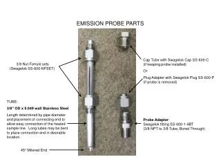
EMISSION PROBE PARTS Cap Tube with Swagelok Cap SS-600-C (if keeping probe installed) Or Plug Adapter with Swagelok Plug SS-600-P (if probe is removed) 3/8 Nut-Ferrule sets (Swagelok SS-600-NFSET) TUBE: 3/8” OD x 0.049 wall Stainless Steel Length determined by pipe diameter and placement of connecting end to allow easy connection of the heated sample line. Long tubes may be bent to place connection end in desirable location. Probe Adapter: Swagelok fitting SS-600-1-4BT (3/8 NPT to 3/8 Tube, Bored Through) 45o Mitered End
EMISSION PROBE INSTALLATION Scribe Line to Identify 45o Mitered Face Weld/braze adapter fitting to exhaust pipe (Do NOT use epoxy as shown in this mock-up) Check the rules regarding probe locations. The probe can NOT be located near the end of the pipe as shown in this mock-up Mitered face in center of pipe and facing upstream
FLOW FLOW FLOW FLOW COUPLER ORIENTATION For all Quick Disconnect couplers (fuel, coolant, supply, return); Flow is out of the male coupler and into the female coupler. NOTE: Contact cagreen@mtu.edu to request couplers (provided free of charge to registered teams).
COOLANT COUPLERS The black, Coolant Couplers shown above have been discontinued. New couplers, white, slightly smaller, and also with a ¾” hose barb, MUST BE USED. The new couplers will not mate with the old style couplers. For information on the new HFC couplers: http://www.colder.com/Products/tabid/693/Default.aspx?ProductId=14
Closed Loop Engine Cooling System Utilizing a brazed plate Heat Exchanger (Closed Loop = Pressure can build up to radiator cap’s relief pressure) Hot Coolant from Engine into Heat Exchanger Cooled Coolant into Engine Inlet line and Outlet line are each 80” long Cold Side of Heat Exchanger Temperature Regulating Valve opens based on the temperature of the coolant returning to the engine
Participant’s Responsibility FUEL SYSTEM for EMISSION TESTING The sled’s fuel tank must be disconnected so that the test facility’s fuel measuring system supplies all the fuel. The test facility will supply a low pressure fuel. Teams need to supply their own external fuel pump and regulator to ensure that the engine receives fuel at the correct pressure. Teams must have the Colder Quick Disconnects installed for both emission events. For the in-service emission event, take into consideration accessibility of the QD’s and routing of the external fuel line(s). The QD’s are not required during the other events in the competition. Questions regarding the emission fuel system requirements should be directed to cagreen@mtu.edu. Colder Female Quick Disconnect OPTIONAL Colder Male Quick Disconnect (if have a return line) Fuel Return Line Engine Fuel Tank Fuel Supply High Pressure PUMP Colder Male Quick Disconnect OPTIONAL Regulator Colder Female Quick Disconnect Fuel Supplied at Low Pressure Test Facility Responsibility Low Pressure 1-5 psi MassFlow Meter Fuel Cooler TransferPump Filter Fuel Supply Low Pressure Fuel Feed to Engine
Facility FUEL System Must measure all fuel consumed during the emission events Fuel Return line (if required) Facility Fuel Return line High Pressure Fuel to Regulator/engine Facility Fuel Supply line 3 -5 psi External Fuel Pump Must be supplied by teams needing Fuel Pressure greater than 3-5 psi During the In-Service Emission Event The facility's fuel lines must run from the engine to the emission test sleigh Fuel Couplers should be located to provide easy access and allow the cowling to be closed during the In-Service emission test.