Download
1 / 55
550 likes | 831 Views
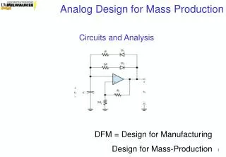
CSE241 VLSI Digital Circuits Winter 2003 Lecture 03: ASIC Flow and Design Convergence. This Class + Logistics. Overview of flow (preparation for Smith Chapters 12-17) Read: Smith Chapter 12 (Synthesis), 13.7 (Static timing) Lab #1 revised due date: Monday January 20 Near-term schedule:

E N D
CSE241VLSI Digital CircuitsWinter 2003Lecture 03:ASIC Flow and Design Convergence
This Class + Logistics • Overview of flow (preparation for Smith Chapters 12-17) • Read: Smith Chapter 12 (Synthesis), 13.7 (Static timing) • Lab #1 revised due date: Monday January 20 • Near-term schedule: • Ben has reserved the lab (EBU I, Room 3329) for this Friday, January 17, noon-1:20pm a running start into synthesis • Recitation #2 tomorrow (noon-12:50pm): not on RTL design, but on datapaths and memories • Lab tomorrow (3:30-5pm): really Lab #1 Slide courtesy of S. P. Levitan, U. Pittsburg
Review • Scaling of gates vs. Scaling of wires • What happens when you make a gate bigger? • What happens when you make a wire taller? Wider? • Coupling • Inductance • How does power/ground distribution affect inductance? • RC delay • Dynamic (useful) power vs. Static (useless) power • How do these issues impact estimates and design approaches? Slide courtesy of S. P. Levitan, U. Pittsburg
Outline • Design types and cost / complexity drivers • Basic flow • On convergence and hierarchy
IC Design Methodologies • Full-Custom (high effort, leading-edge performance, high-volume) • Semi-Custom (strong infrastructure, economical in lower volumes) • ASIC (Application-Specific Integrated Circuit) • COT (Customer-Owned Tooling) • ASIC vs. COT: “Who pays for the scrap?” • FPGA • System-on-a-Chip • Larger components, often from outside of design team • Special • Analog (custom layout, I/Os and sense amps) • Mixed-Signal / RF (unique to each process, no scaling) Slide courtesy of S. P. Levitan, U. Pittsburg
Acceleration of Gate Length Scaling • What are some implications? • Slide courtesy of Numerical Technologies, Inc.
“$1M mask set” in 100nm, but average only 500 wafers per set Mask NRE Cost (1999)
Design Technology Crises, ITRS-2001 Incremental Cost Per Transistor • 2-3X more verification engineers than designers on microprocessor teams • Software = 80% of system development cost (and Analog design hasn’t scaled) • Design NRE > 10’s of $M manufacturing NRE $1M • Design TAT = months or years manufacturing TAT = weeks • Without DFT, test cost per transistor grows exponentially relative to mfg cost Test Manufacturing Manufacturing Turnaround Time SW Design NRE Cost Verification HW Design
Silicon Complexity Challenges • Silicon Complexity = impact of process scaling, new materials, new device/interconnect architectures • Non-ideal scaling (leakage, power management, circuit/device innovation, current delivery) • Coupled high-frequency devices and interconnects (signal integrity analysis and management) • Manufacturing variability (library characterization, analog and digital circuit performance, error-tolerant design, layout reusability, static performance verification methodology/tools) • Scaling of global interconnect performance (communication, synchronization) • Decreased reliability (SEU, gate insulator tunneling and breakdown, joule heating and electromigration) • Complexity of manufacturing handoff (reticle enhancement and mask writing/inspection flow, manufacturing NRE cost)
System Complexity Challenges • System Complexity = exponentially increasing transistor counts, with increased diversity (mixed-signal SOC, …) • Reuse (hierarchical design support, heterogeneous SOC integration, reuse of verification/test/IP) • Verification and test(specification capture, design for verifiability, verification reuse, system-level and software verification, AMS self-test, noise-delay fault tests, test reuse) • Cost-driven design optimization(manufacturing cost modeling and analysis, quality metrics, die-package co-optimization, …) • Embedded software design(platform-based system design methodologies, software verification/analysis, codesign w/HW) • Reliable implementation platforms (predictable chip implementation onto multiple fabrics, higher-level handoff) • Design process management (team size / geog distribution, data mgmt, collaborative design, process improvement)
Outline • Design types and cost / complexity drivers • Basic flow • On convergence and hierarchy
Sylvester-Keutzer: Classic Picture Sylvester-Keutzer, Computer Nov. 99
Behavioral Level Design IO Pad Placement Logic Design and Simulation Power/Ground Stripes, Rings Routing Logic Synthesis Logic Partitioning Die Planning Global Placement Detail Placement Simulation Floorplanning Clock Tree Synthesis and Routing Design Verification Timing Verification Extraction and Delay Calc. Timing Verification Global Routing Test Generation LVS DRC ERC Detail Routing Traditional Flow Front End Back End
Block-Level Design Methodology • Architectural optimization (timing) • Inter-group buses, bandwidth • Clock, SI, test; validation Design Specs Fnl. Design Constraints Synthesis Lib.+CWLM • Floorplanning and custom WLM • Power distribution (Internal, I/O) • I/O driver, padring design • Board-level timing, SI Floor-plan & PG Lib.+CWLM Placement Physical re-synth • Row definitions • Placement of cells • Congestion analysis Clock distribution Route, scan re-order • Placement-based re-synthesis • Noise minimization, isolation • Clock distribution Timing analysis, IPO Fnl., pwr., SI ECO • Full routing • Scan stitching, re-ordering A. Khan, Simplex/Altius Reqmts. ERC, DRC, LVS • Full RC back-annotation • Hierarchical timing, electrical and SI analysis and IPO/ECO Tape-out
Generic Flow Steps • Preparation • Library data preparation • Design data preparation • Logic design • Specification to RTL • RTL simulation • Hierarchical floorplanning • Synthesis • Formal verification • Gate level simulation • Static timing analysis • Physical design • Physical floorplanning • Place and route • RC extraction • Formal verification • Physical verification • Release to manufacturing • Design for test • Engineering change order
Library and Design Data • Models and technology data required to execute the design flow • Power, timing: ALF, DCL, OLA, .lib, STAMP • Layout: LEF, DEF, GDSII • Delays and path timing, parasitics: SDF, GCF, SDC, DSPF, RSPF, SPEF, SPICE • Layout rules: Dracula, Calibre “deck”
Specification to RTL • Defines the logic and fundamental structure of the chip at the RTL level in either the verilog or VHDL language • Requires considerable interaction with the customer, plus specs such as the architecture, system, design, test and block specs • May include RTL from the customer or third party IP providers • Coding guidelines should be established and adhered to, and the code must be compatible with the chosen synthesis tool • Special design considerations such as multiple clock frequencies, asynchronous logic, high speed logic, race conditions, gated clocks, etc. must be addressed
RTL Simulation • RTL code, written in Verilog, VHDL or a combination of both, is simulated to verify functional correctness • Testbenches apply input stimulus to the design • Several methods are used to verify the outputs • Self-checking testbenches automatically verify output correctness and report mismatches • Results can be stored in a file and compared to previous results • Waveform displays can be used to interactively verify the outputs • Verification-specific tools: Verisity Specman, Synopsys Vera • Functional verification • Mostly Modelsim • Cadence’s Verilog-XL or NC-Verilog also used
Hierarchical Floorplanning • Decide on the physical layout strategy—flat or hierarchical? • Advantages of a flat implementation are generally a smaller die size, and a more straightforward approach to clock and power distribution and RC generation • Advantages of a hierarchical design • better runtimes, • better ability to control timing within localized areas of the design, and concurrent design • For hierarchical design, issues • physical partitioning of the logic into blocks • assignment of the physical locations for the block pins • timing budgeting, • distribution of clocks, power • signal bus routing • RC generation • Tool Example: Cadence’s design planner
Floorplanning • Give placement initial clues • Cells that are interconnected want to be close together • Take advantage of RTL hierarchy • Generate a physical hierarchy • RTL hierarchy = best physical hierarchy? • Place big blocks on chip (memories) • Allow space for power/clk/busses • Reduce complexity of placement
Synthesis • Conversion of RTL to gate level netlist • Target foundry specific library • Timing driven methodology • clock information • input arrival times, output required times • Input driving cells, output loading • False paths, multi-cycle paths • Interconnect delay is calculated based on a wireload model which uses fanout to calculate delay • Clocks parameters (insertion delay, skew, jitter, etc.) Are assumed to be attainable later in place and route
Synthesis …contd. • Hierarchical synthesis • Block-by-block basis • Minimizes runtimes • Functional blocks • Tools: • Cadence Buildgates • Synopsys Design Compiler (used for this course)
Formal Verification • RTL description and gate level netlist are compared to verify functional equivalence, thereby verifying the synthesis results • An emerging technology that supplements the more traditional approach of gate level simulation • Tools: • Verplex Tuxedo-lec • Design Verifier (Chrysalis), Mentor FormalPro • Synopsys Formality (will be used in-class)
Gate Level Simulation • Another method to verify the synthesis process, which covers both the functionality and timing • Correctness is only as good as the test vectors that are used • Especially critical for non-synchronous designs, verification of false path and multi-cycle path constraints • Cell timing is included in the simulation models and interconnect delay is passed from the synthesis run • Worst case PVT conditions are used to analyze for setup violations, and best case PVT conditions are used to analyze for hold violations • PVT = Process, Voltage, Temperature • Popular tools are Cadence’s Verilog-XL or NC-Verilog
Static Timing Analysis • Verifies that design operates at desired frequency • Implicitly assumes correct timing constraints (!), e.g., boundary conditions • Timing constraints are similar to those used in synthesis • Verifies setup and hold times at FF inputs; can also check timing from and to PI’s and PO’s; can also check point-to-point delay values (with blocking of pins, etc.) • As with gate-level simulation, both best- and worst-case analysis is performed • Typically performed on full-chip (not block) basis • May require modified constraints for inter-block issues: multiple clock domains, multi-cycle paths, etc. • For compatibility with timing-driven layout flow, helps to have simple / single set of constraints • Other issues: incremental analysis, …
Physical Floorplanning • Defines the basic chip layout architecture • Define the standard cell rows and I/O placement locations • Place rams and other macro cells • Define power bus structures such as power rings and stripes • Often performed using the standard place and route tool • Rules of thumb for cell density are used to initially calculate design size • Popular standalone tools are Cadence’s design planner and avanti’s planet
Place and Route • Automatically place the standard cells • Generate clock trees • Add any remaining power bus connections • Route clock lines • Route signal interconnects • Design rule checks on the routes and cell placements • Timing driven tools • Require timing constraints and analysis algorithms similar to those used during the static timing analysis step • Tools: • Cadence Silicon Ensemble, Synopsys Apollo, Magma Blast Fusion
RC Extraction • Calculates the resistance and capacitance of interconnects • Based on placement of cells • Routing segments • Calculates capacitive effects of adjacent segments • Extracts capacitance between metal segments • RC data is transferred to • Static timing analysis (back annotation) • Gate level simulation • Replaces wire load model used in synthesis • Tools used: • Cadence Hyperextract , Magma’s Blast Fusion • Sequence Columbus, Synopsys Star-RC, Mentor X-Calibre
Signal Integrity • SI • Crosstalk issues • Inductance • Interference • Need new tools • Calculate and estimate SI • New delay models with SI estimates • SI aware routing
Formal Verification • Compares golden netlist to current netlist • Logic equivalence • Comparison of pre- and post-layout netlist • Similar to the formal verification step after synthesis; clock tree insertions, drive strength changes, etc. have been made • Buffer insertion or logic optimization may have been performed
Physical Verification • DRC – Design Rule Check • Polygon/Layer spacing rules • Verifies the design rules (DRC) • LVS – Layout Versus Schematic • Verifies that layout and netlist are equivalent at the transistor level • Antenna • Manufacturing check for long nets • Net can accumulate charge during plasma etch and damage gate oxide • GDSII • Final merge of layout, routing and placement data for mask production • Example tools: • Mentor Graphics Calibre (DRC, LVS) • Cadence Dracula, Diva
Release to Manufacturing • Final edits to the layout are made • Metal fill and metal stress relief rules are checked • Manufacturing information such as scribe lanes, seal rings, mask shop data, part numbers, logos and pin 1 identification information for assembly are also added • DRC and LVS are run to verify the correctness of the modified database • ‘Tapeout’ documentation is prepared prior to release of the GDSII to the foundry • Pad location information is prepared, typically in a spreadsheet • Cadence’s Virtuoso is used for custom-manual edits of the mask layers • Manufacturing steps • generation of masks • silicon processing • wafer testing • assembly and packaging • manufacturing test
Outline • Design types and cost / complexity drivers • Basic flow • On convergence and hierarchy
Evolution of Design Flow • Yesterday 1000nm • Today 130nm • Tomorrow 50nm • System • System • System • System • Design • Model • Design • Model • Functional • Performance • SPEC • Perf. • Hw/Sw • Testability • Model • Optimization • Verification • Functional • Cockpit • Verification • Auto-Pilot • SW • SW • Optimize • RTL • Analyze • Opt • Hw/Sw • Perf. • Comm. • SW • Timing • Synthesis • Hw/Sw • Logic • Power • + Timing Analysis • Data • Circuit • Noise • + Placement Opt • Model • Place • Test • Wire • Mfg. • Performance • Repository • other • other • EQ check • Testability • File • Verification • MASKS • Place/Wire • + Timing Analysis • + Logic Opt • Equivalence checking • File • Multiple design files are converged into one efficient Data Model • Disk accesses are eliminated in critical methodology loops • MASKS • Verification of Function, Performance, Testability and other design • criteria all move to earlier, higher levels of abstraction followed by • equivalence checking and • assertion driven design optimizations • Industry Standard interfaces for data access and control • Incremental modular tools for optimization and analysis • System • Design • Software • Design • Logic • Design • RTL • Synthesis • File • Timing Analysis • Functional • File • Verification • Place/Wire • File • Timing Analysis • Performance • Verification • File • Testability • MASKS • Verification
ARISTO RTL Verilog Hard Blocks Concurrent Block Synthesis Block Shaping, Compaction & Concurrent Port Placement Aristo, DAC-2000 TYPICAL DESIGN FLOW Gate-Level Verilog Library IP Blocks Design Constraints Design Netlist Concurrent Block Partitioning, Clustering & Placement Early Planning Gate-Level Optimization Design Refinement Gate-Level Place & Route Top-Level Routing Chip Assembly RC Extraction Timing Analysis PREDICTABLE HIERARCHICAL DESIGN CONVERGENCE
RTL statistical WLM Behavioral / RTL synthesis timing library Timing logic Route Place Increasing Modeling Detail Monterey, DAC-2000 Design Signoff Physical Prototyping GDSII
Design Closure • Input • RT-level HDL + technology + constraints • Output • “go”: recipe for invocation and composition of SP&R results • “no go”: diagnosis of RTL code problems • Logical and physical hierarchies co-evolve • spatial: top-down coarse placement physical hierarchy • logic/timing: implementable RTL logical hierarchy • limits of human fanout, organizations always have hierarchy • Have seen a natural sequence of no-floorplanning, physical-floorplanning, RTL-floorplanning... as chip complexities increase • Details (must construct, predict, ignore, eliminate, ...) • pin optimizations, interconnect planning, hierarchy reconciliations, budgeting mechanisms, compatibility with downstream SP&R, ...
Logical and Physical Hierarchies • Two hierarchies: logical/functional, and physical • (schematic hierarchy also typical in structured-custom) • RTL design = logical/functional hierarchy • provides valuable clues for physical embedding: datapath structure, timing structure, etc. • can be incredibly misleading (e.g., all clock buffers in a single hierarchy block) • Main issues: • how to leverage logical/functional hierarchy during embedding • when to deviate from designer’s hierarchy • methodology for hierarchy reconciliation (buffers, repartitioning / reclustering, etc.)
Functional Partitioning • Subblocks in A connected with subblocks in B result in • 600 top level nets. Source: ReShape
Physical Partitioning Physical partitioning reduced the number of top level nets from 600 to 0 Source: ReShape
“Natural” Block Shapes • Are not disjoint rectangles, e.g., intersecting timing paths all want to be embedded as “straight paths” • Traditional chip floorplan = dissection into rectangles may not be optimum for wirelength and timing, but has compensating advantages (convenience) Blk A Blk B 1.0 0.5,0.5 1.0
Physical Hierarchy • Physical hierarchy = hierarchical, very structured organization of the core layout region • Potentially, little relation to high-quality (e.g., w.r.t. timing, routability) embedding of logic • Some obvious exceptions • regular structures (memories, PLAs, datapaths) • hard IP blocks • And, physical hierarchy helps to define and plan global interconnects • Recent trend: try to avoid artifactual physical hierarchy created by top-down recursive bipartitioning-based placement approach
Convergence and Predictability • We seek a predictable, estimatable back end (physical implementation after some handoff level of design) • Predictability == regression models? (e.g., wireload models) • Predictability == an enforceable assumption? (“correct by construction”) • constant-delay paradigm (logical effort, DEC, IBM, Magma, ...) • Predictability == fast constructive prediction? (also “correct by construction”) • RT-level (Tera Systems), gate-level flat full-chip (Silicon Perspective Corp. FirstEncounter) • Predictability == remove the need for predictability? • GALS, LIS (global-asynchronous/local-synchronous; latency-independent synchronization) • “protocol- / communication-based system-level design” • Or, just make the loops tighter and easier (“construct by correction”)
Planning Technology • RTL partitioning • understand interaction b/w block definition and placement quality • recognize and cure a physically challenged logic hierarchy • Global interconnect planning and optimization • symbolic route representations to support block plan ECOs • Controllable SP&R back end (including power/clock/scan) • Incremental / ECO optimizations, and optimizations that are “robust” under partial or imperfect design knowledge • Estimators (“initial wireload models”) • to account for resource, topological heterogeneity • to account for optimizations (placement, ripup/reroute, timing) • “earliest RTL signoff with detailed P&R knowledge”
Sequence, DAC-2000 3D Extraction Prepare Database Timing Sign-off Delay True-3D Calculation Parasitics Place Timing Timing RTL Sequence & Synthesis Analysis Analysis Route Interconnect Interconnect Driven Driven Optimization Optimization Driver sizing,topology-based optimization
Constraints complete and block RTLs are feasible Ensure interblock delays are accounted for No iterations from here down Cadence, DAC-2000 RTL, chip constraints Partitioning & Log/Phys Mapping Block Area/Performance Estimation Block Placement Inter-block Routing and Buffering Communication Logic Synthesis Concurrent Placement, Synthesis And Route of Cells in Blocks Finalize Route/Extract/Back Ann.