Download

1 / 68
680 likes | 707 Views
Learn about Limit State Design in structural engineering, IS:800 codes, factors of safety, section classification, and practical design examples. Explore plastic and elastic analysis, beam stability, local buckling, and equations for shear capacity.

E N D
PHILOSOPHY OF LIMIT STATE DESIGNANDCLASSIFICATION OF SECTIONS
What is Limit State? Acceptable limit for the safety and serviceability requirements before failure occurs is called a Limit state
IS : 800 - 1984 Working stress method Factor of safely for yield stress, allowable stresses are less than ‘fy’. Pure elastic approach for analysis of structures under working loads. Yielding or buckling never occurs at working loads Deformations are evaluated at working loads. IS : 800 – 2007 Limit State Method Partial safety factor for material (γm) for yield and ultimate stress. Working loads are factored (increased) as per partial safely factor (γf) causing Limit State of strength. Post buckling and post yielding plays important role in estimating capacity of structural elements at Limit State. Deformations are evaluated at working loads. Highlights
Classification of cross sections • Structural elements in axial compression, bending compression tend to buckle prior yielding. To avoid this, elements of cross section such as width of flange, depth of web of I and channel section, width of legs of angle section, width of flange and leg of Tee section, width and height of Box section need to be proportioned in relation with thickness of element of section.
Classification of cross sections • A table of classification shows three distinct varieties of cross section such as plastic, compact and semi compact section. • Section in which width to thickness ratio exceeds the limits of semi compact section is known as slender section. These sections are to be avoided. • Slender section if at all used needs to ignore excess area to arrive at effective cross section as semi compact section. • If two elements of cross section fall under two different classifications then section is classified into most unfavourable classification.
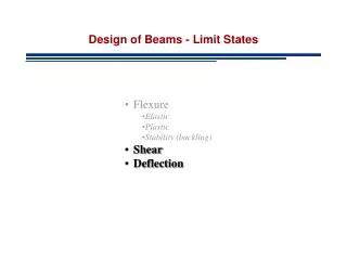
Elastic Analysis Plastic Analysis When factored design shear ≤ 0.6Vd and Flexural membersLaterally supported beam
Conditions to Qualify as a Laterally Restrained Beam • It should not laterally buckle • None of its element should buckle until a desired limit state is achieved • Limit state of serviceability must be satisfied • Member should behave in accordance with the expected performance of the system
Local Buckling In IS:800 (1984) the local buckling is avoided by specifying b/t limits. Hence we don’t consider local buckling explicitly However in IS:800(2007) limit state design, the local buckling would be the first aspect as far as the beam design is concerned How do we consider? By using section classification
Limit states for LR beams • Limit state of flexure • Limit state of shear • Limit state of bearing • Limit state of serviceability
Plastic range Elastic range f fy 2 3 4 Stress Idealised stress strain curve 1 strain Idealized elasto- plastic stress stain curve for the purpose of design
W 1 2 3 4 Plastic Hinge Simply supported beam and its deflection at various stages
MP Moment ‘M’ Effect of strain hardening may occur after large rotation Plastic moment MY Yield moment Curvature Moment curvature characteristics of the simply supported beam
Some typical shape factor 1.5 2.0 1.7 1.27 1.14
Shear yielding near support Web buckling Web crippling
d / 2 b1 n1 450 d / 2 Effective width for web buckling
b1 n2 1:2.5 slope Root radius Effective width of web bearing Web Crippling in beams
Design of Laterally Supported Beam Limit State Method – As per IS: 800 - 2007. Example No : 1 Design a suitable I beam for a simply supported span of 5 m. and carrying a dead load of 20 kN/m and imposed load of 40 kN/m. Take fy = 250 MPa Design load calculations : Factored load = γLD x 20 + γLL x 40 Using partial safety factors for D.L γLD = 1.50 and for L.L γLL = 1.5 (Cl. 5.3.3 Table 4, Page 29)
Total factored load = 1.50 x 20 + 1.5 x 40 = 90 kN/m Factored Bending Moment M = 90 x 5 x 5 / 8 = 281.25 kN.m Zp required for value of fy = 250 MPa and γmo = 1.10 (Table 5, Page 30) Zp = (281.25 x 1000 x 1000 x 1.1) / 250 = 1237500 mm3 = 1237.50cm3 Using shape factor = 1.14, Ze = 1237.50/1.14 =1085.52 cm3 Options ISWB 400 @ 66.7 kg/m or ISLB 450 @ 65.3 kg/m Try ISLB 450 Ze = 1223.8 cm3 1085.52
Geometrical Properties : ISLB 450 D = 450 mm , B = 170 mm , tf = 13.4 mm , tw = 8.6 mm , h1 = 384 mm , h2 = 33 mm Ixx = 27536.1 cm4 As fy = 250 MPa , Section Classification : B/2tf = 85 / 13.4 = 6.34 9.4ε h1 / tw = 384/8.6 = 44.65 < 83.9 ε Section is Classified as Plastic Zp = 1.14 x 1223.8 = 1395.132 cm3
Design Bending Strength: Md > 281.25 kN.m βb = 1.0for plastic section (Cl. 8.2.1.2, Page 53) Check for Serviceability – Deflection Load factor = γLDand γLL = 1.00 both , (Cl. 5.6.1, Page 31) Design load = 20 + 40 = 60 kN/m
Limiting deflection = Span/360 (Table. 5.3, Page52) = 5000/360 = 13.889 mm….OK Hence Use ISLB 450
Working Stress Method IS : 800 - 1984 Max Bending Moment = 60 x 5 x 5/8 = 187.5 kN.m Max Shear Force = 60 x 5/2 = 150 kN Select ISLB 450 Zxx = 1223.8 Moment Capacity = 201.927 kN.m Check for Shear < 100 MPa
Check for Deflection Limiting deflection = Span/325 = 5000/325 = 15.38 mm…OK
Comparison of ISLB 450 Section The Section designed as per LSM is having more reserve capacity for both BM and SF as compared to WSM
Design of Beam with High Shear LSM Example No. 2 Factored Load 100 KN/m A B C ________ 5m_______________ 5m_________
Plastic Analysis Degree of Redundancy = r = 1 No. of plastic hinges required to transform structure into mechanism = r + 1 = 2 Failure of any span is failure of continuous beam. Failure mechanism of AB & BC is identical due to symmetry & this is similar to failure mechanism of propped cantilever beam with udl. wp = 11.656 Mp / l2 Mp = wp.l2 / 11.656 = 100 x 25 / 11.656 = 214.48 KNm.
As both spans fail simultaneously actual no of plastic hings are three – two hinges each at 0.414 l from A & C & third at B. as n = 3 2 required Collapse is over complete Zp = 214.48 x 106 x 1.10 / 250 mm3 = 943.72 cm3 Ze = 943.72 / 1.14 = 827. 82 cm3 Select ISLB 400 Zxx = 965.3 cm3 Md = 1.0 x 1.14 x 965.3 x 250 / 1.10 = 250.1 KNm 214.48
Reaction at A Considering free body of AB Mp = 214.48 KNm Mp + RA x 5 = 100 x 5 x 5/2 RA = 207.1 KN RB1 = 500 – 207.1 = 292.9 KN Due to symmetry in loading Maximum shear is at B = 292.9 KN= V
Vd = 0.577 x 400 x 8 x 250 / 1.1 = 419.636 KN Where 400 x 8 = D.tw of ISLB 400 As V/Vd = 292.9 / 419.636 = 0.697 0.6 As per C1.9.2.2 Page No. 70 Effect of shear is to be considered for reduction in moment capacity Mdv = Md – β(Md – Mfd) β= (2V/Vd – 1)2 = 0.156 Mfd = Plastic moment capacity of flanges only = 165 x 12.5 (400 – 12.5) x 250 / 1.1 = 181.64 KNm Mdv = 250.1 – 0.156 (250.1 – 181.64) = 239.42 KNm As Mdv = 239.42 Mp = 214.48 ------- Ok Select ISLB 400 @ 56.9 kg / m
Laterally supported beam Design of Beams with High Shear by WSM Factored load in LSM is 100 KN/m Working load in WSM = 100 / 1.5 = 66.67 KN/m 66.67 KN/m A 5m B 5m C
Reactions - RB = 5/8 x 66.67 x 10 = 416.66 kN , RA = RC = 125.0 kN Maximum Bending Moment At continuous support = 125.0 x 5 – 66.67 x 5 x 5/2 = -208.33 kN.m Design Shear = 208.33 kN Design Moment = 208.33 kN.m As per IS:800 – 1984, 6bc = 0.66fy = 0.66 x 250 = 165 MPa Z required = (208.33 x 10⁶) / 165 = 1262.62 cm3 Try ISMB 450 @ 72.4 kg/m. Zxx = 1350 cm2 1262.62 Cheak for shear tw = 9.4 mm qav = (208.33 x 1000) / (450 x 9.4) = 49.25 N/mm2 0.4fy i.e. 100 N/mm2
Comparison of WSM vs LSM Design of beam by LSM is more economical
DESIGN OF BEAM COLUMN Combined action of bending and axial force (tension or compression) occurs in following situations. • Any member in a portal frame. • Beam transferring reaction load to column. • Effect of lateral load on a column due to wind, earthquake • Effect of eccentric load by crane loading due to bracket connection to column. • In case of principal rafter, purlins not placed exactly over joint of roof truss.