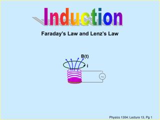
Faraday’s Law
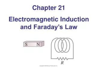
Faraday’s Law. Faraday’s Law of Induction. Faraday’s experiment. When the switch in the primary circuit is closed, the ammeter in the secondary circuit deflects momentarily. The emf induced in the secondary circuit is caused by the changing magnetic field through the secondary coil.


Faraday’s Law
E N D
Presentation Transcript
Faraday’s Law of Induction • Faraday’s experiment. When the switch in the primary circuit is closed, the ammeter in the secondary circuit deflects momentarily. The emf induced in the secondary circuit is caused by the changing magnetic field through the secondary coil.
(a) When a magnet is moved toward a loop of wire connected to a sensitive ammeter, the ammeter deflects as shown, indicating that a current is induced in the loop. (b) When the magnet is held stationary, there is no induced current in the loop, even when the magnet is inside the loop. (c) When the magnet is moved away from the loop, the ammeter deflects in the opposite direction, indicating that the induced current is opposite that shown in part (a). Changing the direction of the magnet’s motion changes the direction of the current induced by that motion.
an electric current can be induced or produced in a circuit (the secondary circuit in our setup) by a changing magnetic field. • The emf induced in a circuit is directly proportional to the time rate of change of the magnetic flux through the circuit. • From this expression, we see that an emf can be induced in the circuit in several ways: • The magnitude of B can change with time. • The area enclosed by the loop can change with time. • The angle θ between B and the normal to the loop can change with time. • Any combination of the above can occur.
Quick Quiz 31.3 • Suppose you would like to steal power for your home from the electric company by placing a loop of wire near a transmission cable, so as to induce an emf in the loop (an illegal procedure). Should you (a) place your loop so that the transmission cable passes through your loop, or (b) simply place your loop near the transmission cable?
Some Applications of Faraday’s Law • The ground fault interrupter (GFI) is an interesting safety device that protects users of electrical appliances against electric shock. • In an electric guitar, a vibrating magnetized string induces an emf in a pickup coil. (b) The pickups (the circles beneath the metallic strings) of this electric guitar detect the vibrations of the strings and send this information through an amplifier and into speakers. (A switch on the guitar allows the musician to select which set of six pickups is used.)
Motional emf • A straight electrical conductor of length l Moving with a velocity v through a uniform magnetic field B directed perpendicular to v. Due to the magnetic force on electrons, the ends of the conductor become oppositely charged. This establishes an electric field in the conductor. In steady state, the electric and magnetic forces on an electron in the wire are balanced. a potential difference is maintained between the ends of the conductor as long as the conductor continues to move through the uniform magnetic field
A conducting bar sliding with a velocity v along two conducting rails under the action of an applied force Fapp. The magnetic force FBopposes the motion, and a counterclockwise current I is induced in the loop. (b) The equivalent circuit diagram for the setup shown in part (a). • Motional emf
Lenz’s Law The induced current in a loop is in the direction that creates a magnetic field that opposes the change in magnetic flux through the area enclosed by the loop. As the conducting bar slides on the two fixed conducting rails, the magnetic flux due to the external magnetic field into the page through the area enclosed by the loop increases in time. By Lenz’s law, the induced current must be counterclockwise so as to produce a counteracting magnetic field directed out of the page. When the bar moves to the left, the induced current must be clockwise. Why?
(a) When the magnet is moved toward the stationary conducting loop, a current is induced in the direction shown. The magnetic field lines shown are those due to the bar magnet. (b) This induced current produces its own magnetic field directed to the left that counteracts the increasing external flux. The magnetic field lines shown are those due to the induced current in the ring.
(c) When the magnet is moved away from the stationary conducting loop, a current is induced in the direction shown. The magnetic field lines shown are those due to the bar magnet. (d) This induced current produces a magnetic field directed to the right and so counteracts the decreasing external flux. The magnetic field lines shown are those due to the induced current in the ring.
Generators and Motors • (a) AC generator, schematic diagram of an AC generator. An emf is induced in a loop that rotates in a magnetic field. (b) The alternating emf induced in the loop plotted as a function of time.
A loop enclosing an area A and containing N turns, rotating with constant angular speed ω in a magnetic field. The emf induced in the loop varies sinusoidally in time.
DC generator, the components are essentially the same as those of the AC generator except that the contacts to the rotating loop are made using a split ring called a commutator. The magnitude of the emf varies in time but the polarity never changes.
Eddy Currents • As we have seen, an emf and a current are induced in a circuit by a changing magnetic flux. In the same manner, circulating currents called eddy currents are induced in bulk pieces of metal moving through a magnetic field. • As the plate enters or leaves the field, the changing magnetic flux induces an emf, which causes eddy currents in the plate.
(a) As the conducting plate enters the field (position 1), the eddy currents are counterclockwise. As the plate leaves the field (position 2), the currents are clockwise. In either case, the force on the plate is opposite the velocity, and eventually the plate comes to rest. (b) When slots are cut in the conducting plate, the eddy currents are reduced and the plate swings more freely through the magnetic field.
Quick Quiz • In equal-arm balances from the early twentieth century, it is sometimes observed that an aluminum sheet hangs from one of the arms and passes between the poles of a magnet. This causes the oscillations of the equal-arm balance to decay rapidly. In the absence of such magnetic braking, the oscillation might continue for a very long time, so that the experimenter would have to wait to take a reading. The oscillations decay because (a) the aluminum sheet is attracted to the magnet; (b) currents in the aluminum sheet set up a magnetic field that opposes the oscillations; (c) aluminum is paramagnetic.
Maxwell’s Equations • We conclude this chapter by presenting four equations that are regarded as the basis of all electrical and magnetic phenomena. These equations, developed by James Clerk Maxwell, are as fundamental to electromagnetic phenomena as Newton’s laws are to mechanical phenomena. • 1st equation, Gauss’s law, the total electric flux through any closed surface equals the net charge inside that surface divided by ε0. This law relates an electric field to the charge distribution that creates it.
2ndequation, which can be considered Gauss’s law in magnetism, states that the net magnetic flux through a closed surface is zero. That is, the number of magnetic field lines that enter a closed volume must equal the number that leave that volume. This implies that magnetic field lines cannot begin or end at any point. • 3th equation is Faraday’s law of induction, which describes the creation of an electric field by a changing magnetic flux. This law states that the emf, which is the line integral of the electric field around any closed path, equals the rate of change of magnetic flux through any surface area bounded by that path. One consequence of Faraday’s law is the current induced in a conducting loop placed in a time-varying magnetic field.
4th equation, usually called the Ampère–Maxwell law, is the generalized form of Ampère’s law, and describes the creation of a magnetic field by an electric field and electric currents: the line integral of the magnetic field around any closed path is the sum of times the net current through that path and μ0ε0 times the rate of change of electric flux through any surface bounded by that path.
Self-Inductance • After the switch is closed, the current produces a magnetic flux through the area enclosed by the loop. As the current increases toward its equilibrium value, this magnetic flux changes in time and induces an emf in the loop. • This effect is called self-induction because the changing flux through the circuit and the resultant induced emf arise from the circuit itself. The emf εLset up in this case is called a self-induced emf (back emf).
(a) A current in the coil produces a magnetic field directed to the left. (b) If the current increases, the increasing magnetic flux creates an induced emf in the coil having the polarity shown by the dashed battery. (c) The polarity of the induced emf reverses if the current decreases • a self-induced emf is always proportional to the time rate of change of the current
L is a proportionality constant—called the inductance of the coil—that depends on the geometry of the coil and other physical characteristics • The SI unit of inductance is the henry (H), which is 1 volt-second per ampere:
example Find the inductance of a uniformly wound solenoid having N turns and length l. Assume that l is much longer than the radius of the windings and that the core of the solenoid is air. • We can assume that the interior magnetic field due to the current is uniform and given by • where n = N/l is the number of turns per unit length. The magnetic flux through each turn is • where A is the cross-sectional area of the solenoid. Using this expression we find that
RL Circuits • A series RL circuit. As the current increases toward its maximum value, an emf that opposes the increasing current is induced in the inductor. • we can apply Kirchhoff’s loop rule to this circuit, traversing the circuit in the clockwise direction
Plot of the current versus time for the RL circuit shown in figure. The switch is open for t < 0 and then closed at t = 0, and the current increases toward its maximum value ε/R. The time constant τ is the time interval required for I to reach 63.2% of its maximum value Plot of dI/dt versus time for the RL circuit shown in figure. The time rate of change of current is a maximum at t = 0, which is the instant at which the switch is closed. The rate decreases exponentially with time as I increases toward its maximum value.
An RL circuit. When the switch S is in position a, (enough to allow the current to reach its equilibrium value ε/R) the battery is in the circuit. When the switch is thrown to position b, the battery is no longer part of the circuit.
Current versus time for the right-hand loop of the circuit shown in figure. For t < 0, the switch S is at position a. At t = 0, the switch is thrown to position b, and the current has its maximum value ε/R.
Quick Quiz 32.3 • The circuit in figure includes a power source that provides a sinusoidal voltage. Thus, the magnetic field in the inductor is constantly changing. The inductor is a simple air-core solenoid. The switch in the circuit is closed and the lightbulb glows steadily. An iron rod is inserted into the interior of the solenoid, which increases the magnitude of the magnetic field in the solenoid. As this happens, the brightness of the lightbulb (a) increases, (b) decreases, (c) is unaffected.
example • Find the time constant of the circuit shown in figure. • The switch in figure is closed at t = 0. Calculate the current in the circuit at t = 2.00 ms. • Compare the potential difference across the resistor with that across the inductor.
Mutual Inductance • A cross-sectional view of two adjacent coils. A current in coil 1 sets up a magnetic field and some of the magnetic field lines pass through coil 2. • mutual inductance M12 of coil 2 with respect to coil 1: • If the current I1 varies with time, we see from Faraday’s law that emf induced by coil 1 in coil 2 is
If the current I2 varies with time, the emf induced by coil 2 in coil 1 is • In mutual induction, the emf induced in one coil is always proportional to the rate at which the current in the other coil is changing. Thus, with M12 = M21 = M • These two equations are similar in form to equation before for the self-induced emf ε = -L(dI/dt). The unit of mutual inductance is the henry.
quiz 1. A circular coil having ten turns and a radius of 120 mm is placed with its plane parallel to the earth’s magnetic field. A compass needle placed at the center of the coil points at an angle of 45o with the plane of the coil when a current of 0.45A flows through the coil. Calculate the intensity of the earth’s magnetic field. 494 2. A long wire carries a current of 20 A along the directed axis of a long solenoid. The field due to the solenoid is 4 mT. Find the resultant field at a point 3 mm from the solenoid axis.496 3. The wire shown in figure carries a current of 40 A. find the field at point P. 497