Download
1 / 56
570 likes | 771 Views
K. Long, 26 October 2014. Proposal for a programme of Neutrino Factory R&D. Bath, RMCS Shrivenham, Daresbury, Glasgow, Liverpool, Imperial College, Oxford, RAL, QMUL, Sheffield High Power RF Faraday Partnership. Introduction. Neutrino Factory: physics case.

E N D
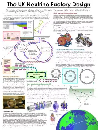
K. Long, 26 October 2014 Proposal for a programme of Neutrino Factory R&D Bath, RMCS Shrivenham, Daresbury, Glasgow, Liverpool, Imperial College, Oxford, RAL, QMUL, Sheffield High Power RF Faraday Partnership Introduction
Neutrino Factory: physics case • Neutrino oscillations – established exptly • Implications for particle physics: • Neutrino mass > 0 • CP violation in the lepton sector? • Impact on astrophysics and cosmology: • Origin of matter (leptogenesis) • Dark matter • Require dedicated exptl programme to: • Search for leptonic-CP violation • Precisely measure parameters
NF: UK contributions to date - Proton driver: • Schemes for: • RAL: • NF and ISIS upgrades based on RCS • CERN: • RCS in ISR tunnel • Contribution to SPL • Fermilab: • Contribution to design of 8 GeV booster • J-PARC: • Contribution to 3 GeV proton ring
NF: UK contributions to date 5 MW proton driver developed from ISIS synchrotron
NF: UK contributions to date CERN: 30 GeV rapid cycling synchrotron in the ISR tunnel - Proton driver:
NF: UK contributions to date Data taking complete • HARP: • Target assembly • Software • Leadership in analysis • Target system: • Power dissipation and thermal shock: • Rotating solid band (see R. Bennett) • Particle production and capture - Targetry:
NF: UK contributions to date Data taking complete - Muon front end: • Ionisation cooling: • Principle:: • MuScat:Measure MCSdistributions • Practice: • MICE • Simulation: • Ring coolers • Alternatives
NF: UK contributions to date - international Muon Ionisation Cooling Expt: 142 authors, 37 institutes, 3 continents!
NF: UK contributions to date - MICE
The vision: neutrino physics • Prepare for era of precision neutrino physics • Worldwide consensus: • Neutrino Factory physics programme is: • Of fundamental importance • Complementary to that of LHC and LC • Neutrino Factory is the tool of choice • Therefore likely that it will be built. So:
The vision: UKNF proposal 2003 • Programme of accelerator R&D that will: • Give the UK ownership of the key technologies: • Proton driver front end • Targetry • Ionisation cooling • Conceptual design of complete facility: • Embed results of hardware R&D • Optimise entire complex • This will position UK to : • Position UK to play lead role • Possibly also to bid to host the facility
UK Neutrino Factory R&D activity R. Edgecock UKNF WP1Conceptual design WP2Proton driver front end WP3Target studies WP4Neutrino Factory design studies MICE-UK R. Bennett D. Findlay
UK Neutrino Factory R&D activity Present request Present request 05/06 05/06 07/08 07/08 09/10 09/10 06/07 06/07 09/09 09/09 04/05 04/05
Front end test stand — WP2 • Work package manager: • David Findlay • Accelerator Division • ISIS Department • Rutherford Appleton Laboratory • Michael Clarke-Gayther • Alan Letchford • John Thomason
Strong overlap • Why interest in front end? • Front end of machine is where • currents and duty cycles are set for whole machine • beam quality is set for whole machine • UKNF: 4 MW — Front end must be good! • Multi-megawatt proton accelerators are new • Neutrino factories • Neutron sources, transmutation,tritium, energy, etc. • 1 W/m loss max., ~10—7 loss per metre
Neutrino factory proton driver: • Ion source (65 mA) • LEBT (low energy beam transport) • RFQ (75 keV 2.5 MeV, 280 MHz) • Chopper (typically ~30% chopped out) • DTL (2.5 MeV 180 MeV, 280 MHz) • Achromat • Synchrotrons • Front end must be good, so need a front end test stand to make sure! Front end
Ion source: H—, 65 mA, 400 µs • 2 × 2 × world’s leading H— source — ISIS • Existing negative ion source development programme at RAL for HPPAs in general • ASTeC • EU (network HPRI-CT-2001-50021) • This ion source programme a benefit to UKNF front end test stand programme
LEBT and RFQ • Low energy beam transport • Matches 65 mA from ion source to RFQ • RFQ • 4-rod, 75 keV 2.5 MeV, 280 MHz • These less of a problem • Can base on experience of LEBT and RFQ for ISIS and outline designs for ESS • More a matter of implementation than R&D • But ~1–2 MW RF driver required for RFQ
Why chopper? Ion source Linac Ring Beam loss >10 × ISIS Bunching Also to minimise RF transients and control beam intensity
With chopper — gaps in beam Ion source Linac Ring No beam loss Bunching
Chopper performance required DC accelerator RF accelerator ns – µs spacing UKNF: 280 MHz, bunch spacing 3.57 ns Switch between bunches Good On Off Bad Partially chopped bunches a problem! Tune shifts!
Choppers across the world: • SNS 402 MHz, slow — only chopper built • CERN 352 MHz, SPL — work proceeding • RAL 280 MHz, fast, rugged, “UK” LEBT MEBT SNS, 2½ ns per bunch
RAL aspiration:switch in 2 ns and dissipate ~3–4 kW when “off” 2-stage process Slow transmission line 0 1 0 1 Lumped line — thermally hardened 2 ns 8 ns
RAL beam chopper— outline scheme Beam ~1 m Fast switch Buncher cavity Slow switch Buncher cavity Need to build andtest with bunched beam
Build test stand • Ion source (R&D already • under way) • LEBT • RFQ (bunches beam) • Chopper • Diagnostics Experience of building test stands at RAL — ISIS RFQ test stand
Front end test stand at RAL — 3 and 6 year costs SY £k (hardware incl. VAT + contingency) Overall design + infrastr. 8 8 398 398 Ion source 6 7 324 347 LEBT 2 5 139 231 RFQ 1 14 46 1388 Chopper 14486231990 1530 4355 hardware 65 185 travel 30 82 16314495 staff 3226 9035 total
Front end test stand at RAL • Six-year programme to build • Costed on basis of test stand already built and working • ~£4½M equipment • ~80 staff-years • RAL + university staff • Physics and engineering of real accelerator facility
Proposal for a programme of Neutrino Factory research and development WP-3 The Target The Neutrino Factory Target Work Package Manager - J R J Bennett CCLRC, RAL
ps/ms to the muon front-end proton beam 4 MW target 1 MW beam dump 3 MW pion collector solenoids thick shield walls Schematic diagram of the target and collector area
Parameters Proton Beam pulsed 10-50 Hz pulse length 1-2 ms energy 2-30 GeV average power ~4 MW Target (not a stopping target) mean power dissipation 1 MW energy dissipated/pulse 20 kJ (50 Hz) energy density 0.3 kJ/cm3 (50 Hz) 2 cm 20 cm beam
Target Developments – so far • Mercury Jets (USA and CERN) • Contained Flowing Mercury • Granulated Targets (CERN) • Solid targets (USA and RAL) • Solid Rotating Ring (USA and RAL) • The mercury jets have had most development • All schemes have advantages and disadvantages
The RAL scheme Large rotating toroid cooled by Thermal Radiation This is very effective at high temperatures due to the T4 relationship (Stefans law).
Schematic diagram of the radiation cooled rotating toroidal target rotating toroid toroid magnetically levitated and driven by linear motors solenoid magnet toroid at 2300 K radiates heat to water-cooled surroundings proton beam
POWER DISSIPATION 3 1 10 10000 m v = 100 m/s 1000 m 100 2000 m v = 20 m/s 100 m 200 m v = 10 m/s 1000 m 10 power MW 20 m 100 m 10 m v = 1 m/s 10 m 100 m 2 m 1 10 m v = 0.1 m/s 1 m 1 m 10 m 0.1 1 m 0.1 m 0.1 m 0.01 3 0.01 0.1 1 10 100 1 10 radius/velocity 5m radius 10 m/s velocity
Simple explanation of shock waves 2d short pulse of protons target the temperature rises by ΔT Time t = 0 inertia prevents the target from expanding until: Short pulse of protons compression t > 0 Δd the target expands by Δd (axially) tension velocity V vis the velocity of sound in the target material.
Shock, Pulse Length and Target Size If a target is heated uniformly and slowly – there is no shock! Or, when the pulse length t is long compared to the time t taken for the wave to travel across the target – no shock effect! So, if we make the target small compared to the pulse length there is no shock problem. For the case of the neutrino factory target: Assume t = 2 ms, V = 3.3x105 cm s-1 , then d = 0.7 cm Energy density is the key parameter
Proposed R&D • Calculate the energy deposition, radio-activity for the target, solenoid magnet and beam dump. • Calculate the pion production (using results from HARP experiment) and calculate trajectories through the solenoid magnet. • 2. Model the shock • a) Measure properties of tantalum at 2300 K • b) Model using hydrocodes developed for • explosive applications at LANL, LLNL, AWE etc. • c) Model using dynamic codes developed by • ANSYS
Proposed R&D, continued 3. Radiation cooled rotating toroid a) Calculate levitation drive and stabilisation system b) Build a model of the levitation system 4. Individual bars a) Calculate mechanics of the system b) Model system 5. Continue electron beam tests on thin foils, improving the vacuum 6. In-beam test at ISOLDE - 106 pulses 7. In-beam tests at ISIS – 109 pulses 8. Design target station
Levitated target bars are projected through the solenoid and guided to and from the holding reservoir where they are allowed to cool. proton beam solenoid collection and cooling reservoir
Equipment and Staff Costs over the first 3 years (excluding VAT)
Time scale Decision on solid target
Effective target length ~20 cm Proton beam Mercury jet Solenoid Schematic diagram of the mercury jet target
To mercury pump & heat exchanger Protons 20 T solenoid magnet Tube containing flowing mercury Schematic diagram of the contained flowing mercury target