Download
1 / 13
130 likes | 261 Views
SK E Y E BALL: REAL-TIME VISION SYSTEM FOR AN AUTONOMOUS MODEL AIRPLANE Danko Antolovic Pervasive Technology Laboratory, Indiana University, Bloomington Bryce Himebaugh Steven D. Johnson Department of Computer Science, Indiana University, Bloomington. Goals and Objectives of Skeyeball:

E N D
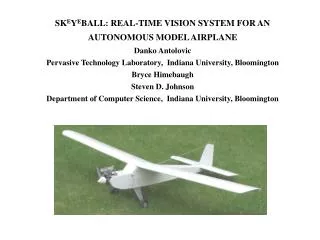
SKEYEBALL: REAL-TIME VISION SYSTEM FOR AN AUTONOMOUS MODEL AIRPLANE Danko Antolovic Pervasive Technology Laboratory, Indiana University, Bloomington Bryce Himebaugh Steven D. Johnson Department of Computer Science, Indiana University, Bloomington
Goals and Objectives of Skeyeball: - Situated vision research: - situational awareness => vehicle autonomy - navigation - target tracking - collision avoidance (obstacles, terrain, other UAVs) - Development of tools and methods for reliable embedded design: - e.g. SPIDER avionics, under development at NASA/LRC - Development of a platform for undergrad/graduate education
Situated computer vision • Why? • -Vision is an ill-posed problem • -Research has lead to a profusion of algorithms, many ill-suited for control and guidance applications • Situated application places stringent constraints on algorithms and hardware architecture. A situated vision system must be: • Embedded, i.e. compact and mobile • Real-time • Integrated into the control loop(s)
The Vision Funnel 9.3 Mbytes/sec thresholding edge detection Data reduction by a factor of 10,000,000 segmentation (logical analysis) target identification YES/NO ? (~10 times/sec)
Start with a gray-scale aerial shot … … threshold it to B/W
… trace edges … segment the edge map into connected components
… calculate moments of inertia for each component Moments are invariant under rotations and translations. Move the camera to bring the target in the center of the vision field.
servo data diagnostics 16 Parallel port Serial port duty cycles 2 Servo duty cycles servo motion MCF5307 IRQ5 XC4010 FPGA back end B/W threshold Unified cache (DRAM only) PIC16F877 DRAM(8M) video & threshold controls 4 8 4 Servo position (analog) 4 enable sigs. 8 15 Servos addr data sync signals enable sigs. LM1881 2 7 Camera XC4010 FPGA front end addr 15 CY7C007AV DPRAM(32K) NTSC digitized video data 8 AD876 8 sampling clk. To ground station (RF) Architecture of the Vision Hardware
Measurement of the tracking speed Maximum sweeping rate: 45 deg./sec, more than adequate for the airplane’s overflight speeds and a camera field of ca. 50 deg.
High-Priority Objectives … • - stable and unambiguous aerial tracking • an orbiting mode, in which the aircraft autonomously circles above (or follows) an acquired target • - collision avoidance capability for stationary obstacles, to be extended in the future to avoidance of other UAVs


![[Report] Real-Time Marketing: The Agility to Leverage 'Now' by Rebecca Lieb](https://cdn4.slideserve.com/7672878/a-market-definition-report-real-time-marketing-dt.jpg)