Download
1 / 36
390 likes | 529 Views
Using the IEEE Comprehensive Test Feeder W. H. Kersting. Purpose of the Test Feeder. Requires Modeling of all possible Overhead lines Underground lines Voltage regulator connections Transformer connections Induction machines Secondary systems

E N D
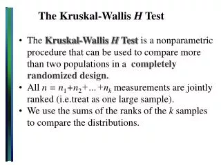
Purpose of the Test Feeder • Requires Modeling of all possible • Overhead lines • Underground lines • Voltage regulator connections • Transformer connections • Induction machines • Secondary systems • Provides a teaching tool for the new distribution engineer
Overhead Lines • Three-phase 4 wire • Three-phase 3 wire • Two-phase 3 wire • Two-phase 2 wire • Single-phase 2 wire • Single-phase triplex • Three-phase quadraplex • Parallel lines
Underground Cable Lines • Three 1/3 concentric neutral cables + 1 ground wire • Three 1/3 concentric neutral cables • Two concentric neutral cables with full neutrals • Two tape shielded cables + 1 ground wire • One full concentric neutral cable
Transformer Connections • Three-phase with and without center tap • Grd. Y – Grd Y • Grd. Y – D • Ungrd. Y – D • D – Grd. Y • Open Y – D • Open D – D • Single-phase with and without center tap • Grd. Y – D • D – Grd. Y (no center tap) • D - D
Step Voltage Regulators • Three single-phase connected • Y – Y • D – D • Two single-phase connected: • Open D – Open D • One single-phase connected Grd. Y
Induction Machines • Three-phase generator with specified kW • Three-phase motor with specified slip • Three-phase motor with specified kW • Three-phase motor with specified kW and power factor
Loads • Spot and Distributed (ZIP Loads) • Y with specified kW and kvar • Y with specified Z • Y with specified current • D – with specified kW and kavr • D – with specified Z • D – with specified current
Parallel Lines • Overhead on common pole • Common sending end node • Separate receiving end nodes • Underground cables • In common trench • Common sending end node • Receiving end • Common • Or separate
Voltage Regulation • All customer voltages within ANSI standard of between 126 and 114 volts • Voltage regulator settings • Voltage level – desired voltage at the load center • Compensator R and X settings – equivalent impedance between regulator and the load center • Bandwidth –
Substation Regulator • Three single-phase connected Y – Y • Load center node 717 • Voltage level = 123 volts • R + jX = 4.7 + j3.4 volts • Bandwidth = 2 volts • Load center(node 717) voltages = 121.9, 122.5 and 121.6 • Final taps = +12, +10 and + 12
Node 735 voltages = 115.1, 117.4 and 114.0 Low Voltages
How To Correct Low Voltages • Shunt capacitors at node 731 • 900 kvar three-phase • Voltages still low • New voltage regulator at node 717 • CT primary ratio = 200 • PT ratio = 120 • Load center = node 735 • Voltage level = 122 volts
Compensator R & X Settings • Node voltages and line currents
Reg – 4 Settings • Voltage Level = 125 • R = 1.3 volts • X = 0.5 volts • Bandwidth = 2 volts
Transformer Connections • Grounded Y-D Open Y - D • Ungrounded Y -D
UG Current Flows • With SW-3 closed • With SW-3 Open
Induction Generator Studies • Transformer T9 Connections • Delta-Delta • Ungrounded Wye – Delta • Grounded Wye – Delta • Generator – Delta Connected • On – Supplying 150 kW to the system • Off
Delta – Delta Connection • Generator On: • Generator Off:
Ungrounded Wye - Delta • Generator On: • Generator Off:
Grounded Wye - Delta • Generator On: • Generator Off:
IEEE Test Feeders Web Site • http://ewh.ieee.org/soc/pes/dsacom/testfeeders/index.html
Summary • IEEE Comprehensive Feeder Studied • Can be used to teach new engineers how the feeder operation changes with changes in the various devices • Good for “what if” questions • The IEEE Test Feeder Task Force hopes the system will be used not only by new engineers but by program developers to confirm results